Fabrication · Light Data Bars
Part 2a - The LED frame (CNC Milling)
Workflow explanations
For this part of the project, it is advised that you first contact the person who will operate the machines to produce the output. This because every machine has its own specs, capabilities, and possibly even software. The following paragraphs show the workflow that works for the specific machine used to produce our prototype, a Stepcraft 2/800. This is why you will notice that the LED frame is produced in two blocks, which are then assembled together: the machine building plate of the Stepcraft 2/800 isn't big enough to produce the whole LED frame in a single operation. The machines you have access to, on the other hand, might allow you to produce the whole frame in a single code, or require you to break down the GCode to produce smaller sections in each milling operation like our case. Always ask the machine operator for assistance in breaking the 3D model into smaller sections depending on what their machine can handle.
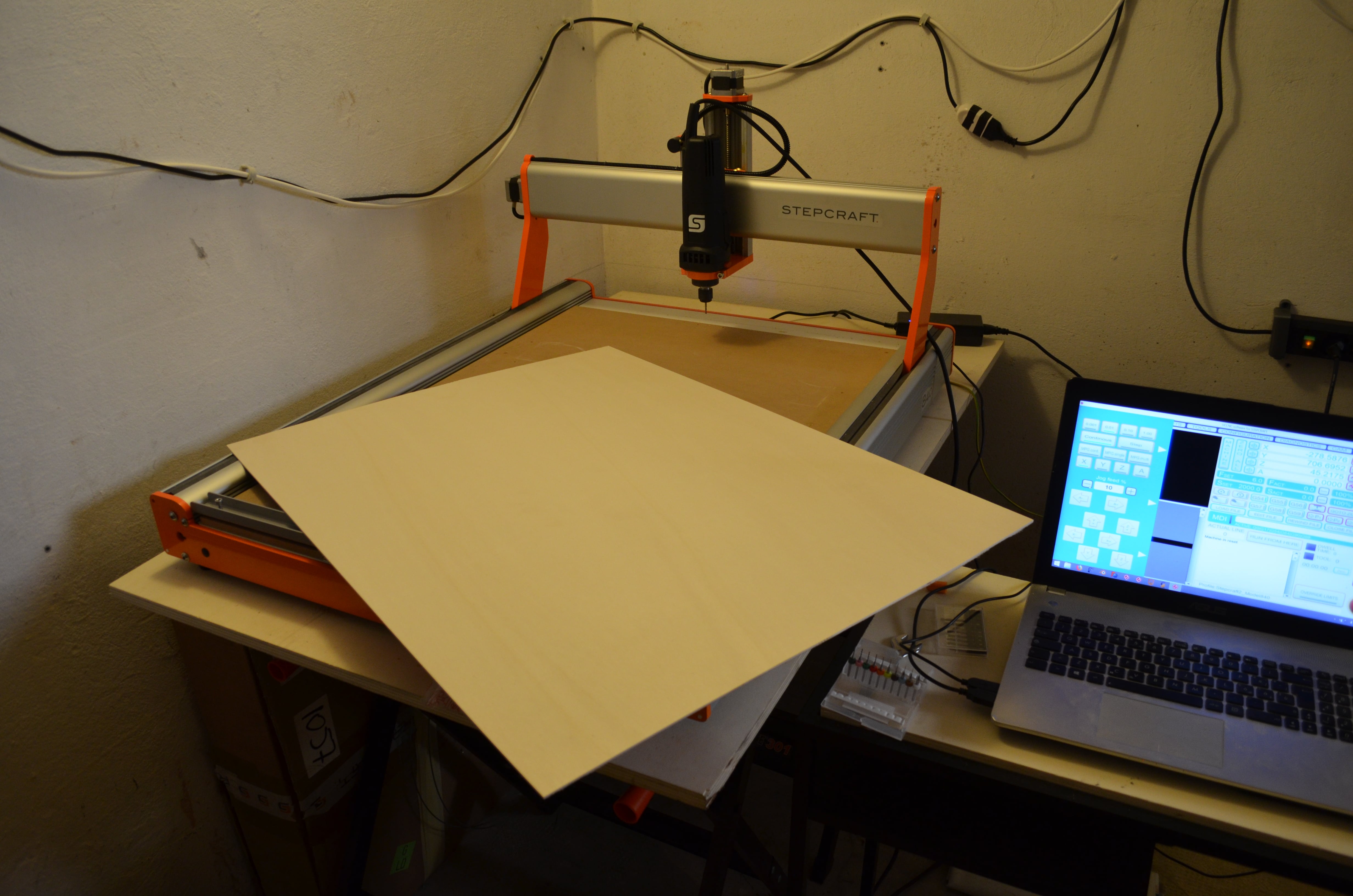
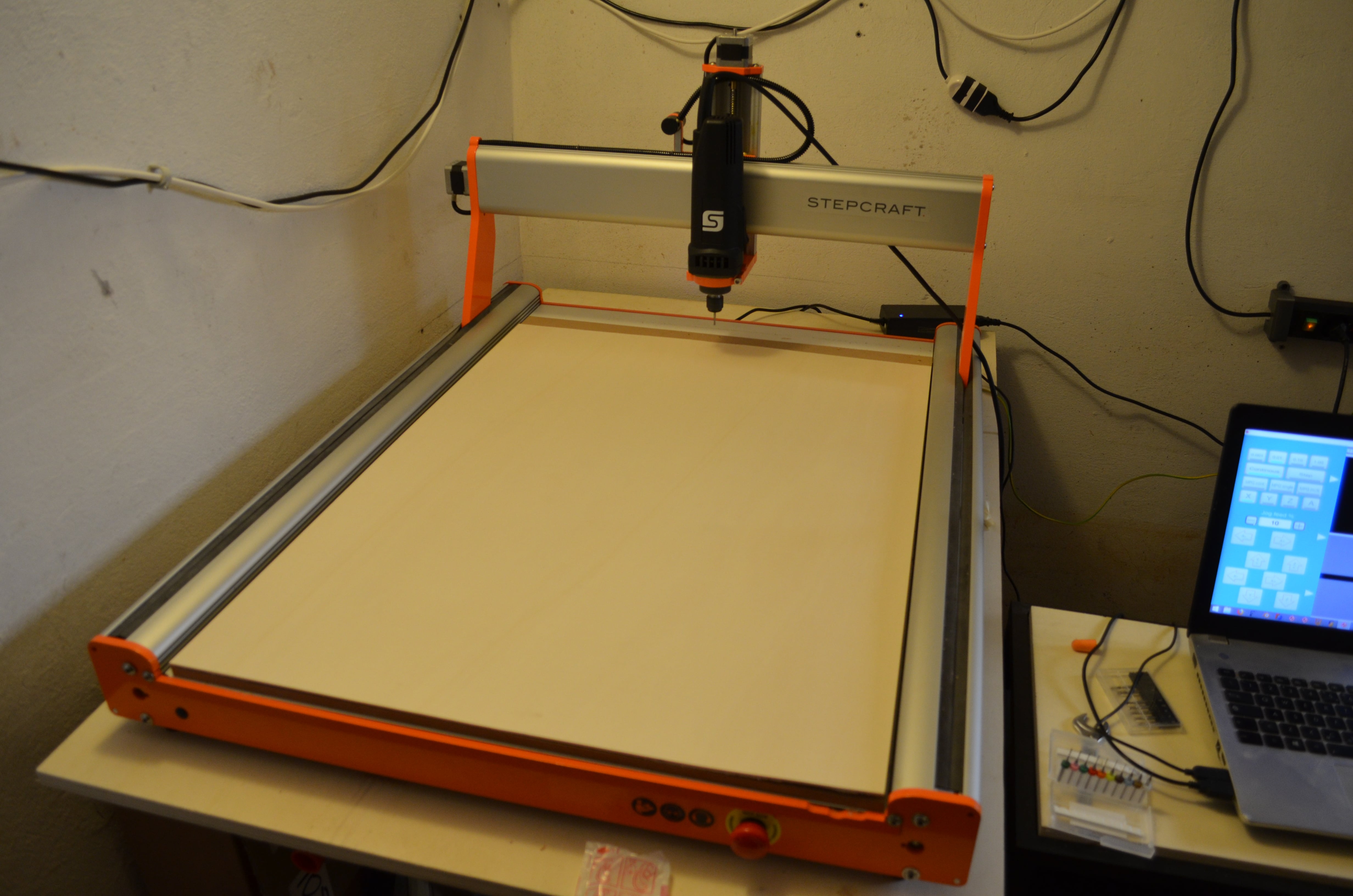
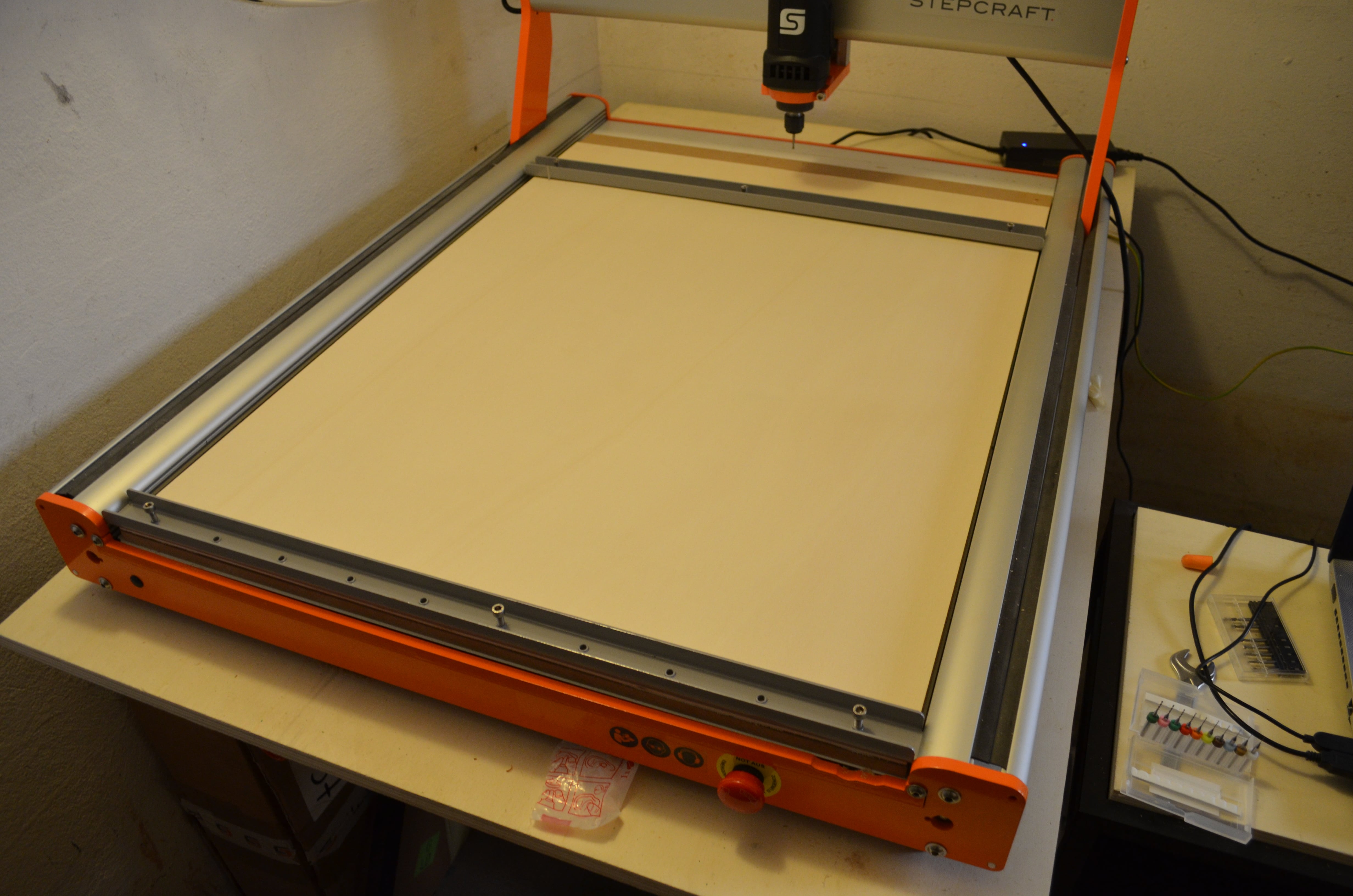
1. Place the first wood sheet on the surface of the CNC milling machine. Make sure the machine has a so-called “sacrificial layer”, usually a piece of MDF which will protect the actual surface of the machine from accidental collisions with the milling tool. When the wood sheet is in position, check that it rests completely flat on the sacrificial layer, without any bump.
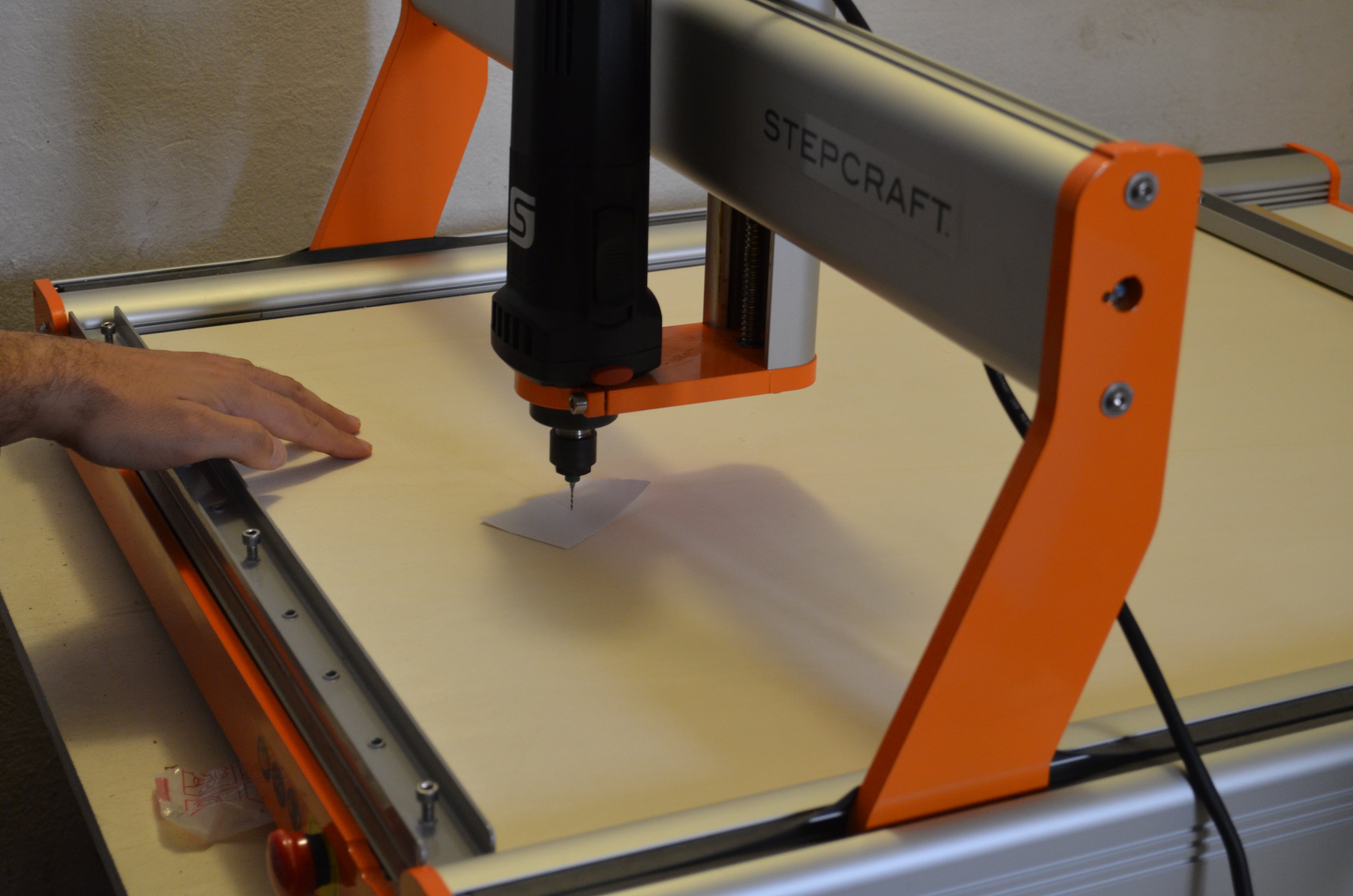
2. Once the sheet is laying place, it need to be fixed in place so that it doesn’t move around during the milling operation. Many machines will have something, screwable bars in the Stepcraft 2/800 shown in the picture, that firmly attach the material to the machine. If this support is missing, you can screw the wood sheet that you will mill directly to the machine’s sacrificial layer, being extra careful that the screws are not placed in areas where the milling tool will move upon.
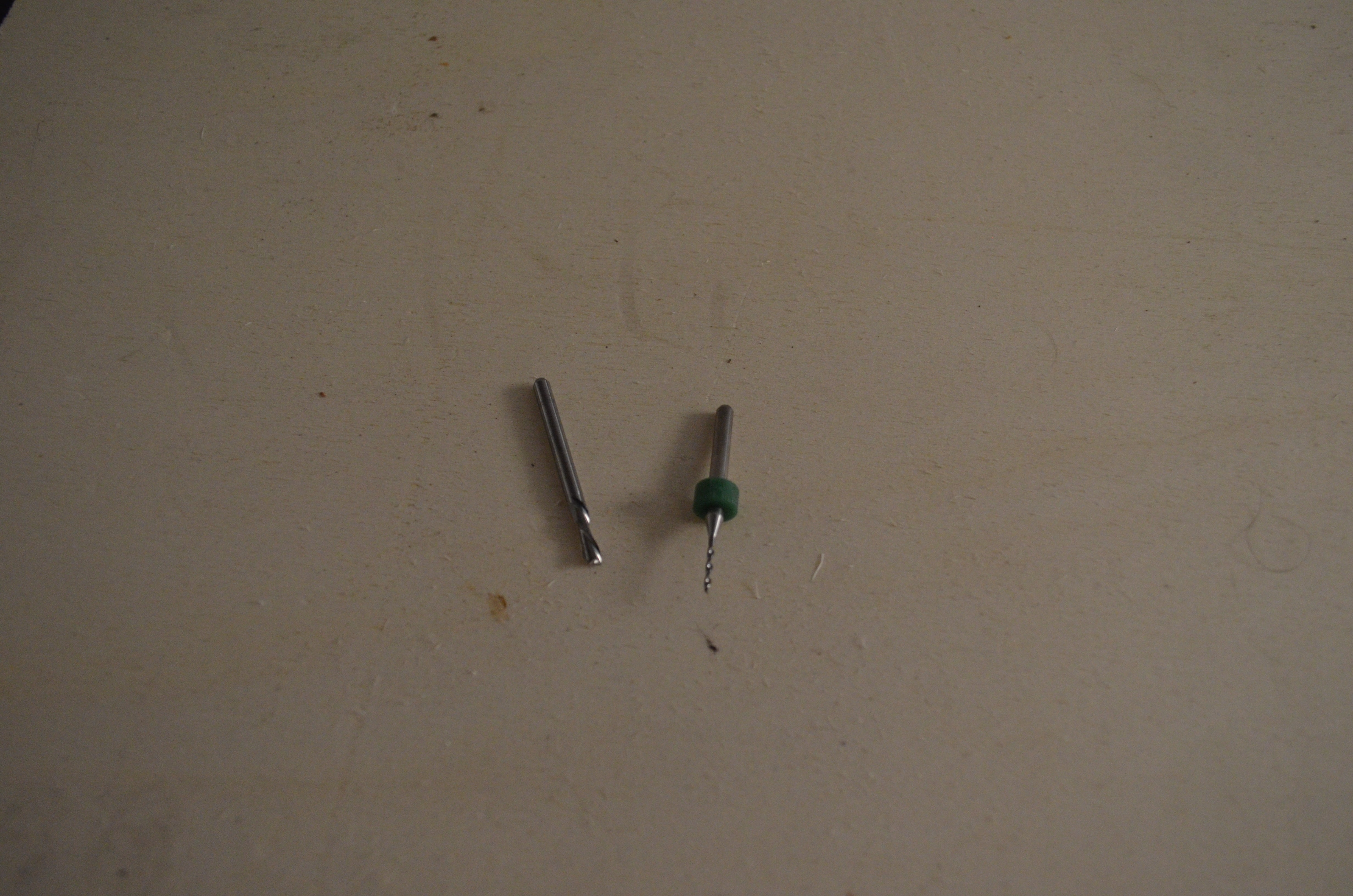
3. Pick the milling tools needed for your project. You might remember that you had already assigned them in FreeCAD, from the
4. Now set the origin point for the spindle’s movements. Again, this should match the position you had set in FreeCAD, when generating the GCode and defining the stock. So, if in FreeCAD you had set the origin in the bottom left corner, now you should position the spindle in the bottom left corner, so that the paths followed by the spindle do not exceed the work surface. The origin point consists of a X, a Y and a Z coordinate point. Unless it’s a very complicated pattern, you can set the position along the X and Y axis also simply by eye-measurement. The position along the Z axis, that is how high the milling bit is from the surface of the working material, is a bit more complicated. Some machines have an automatic system for this positioning. Otherwise, an accurate positioning can be obtained manually, by placing a regular sheet of paper underneath the tip of the milling tool and moving the spindle down until the milling tool touches the paper. You will know you have reached the correct positioning when:
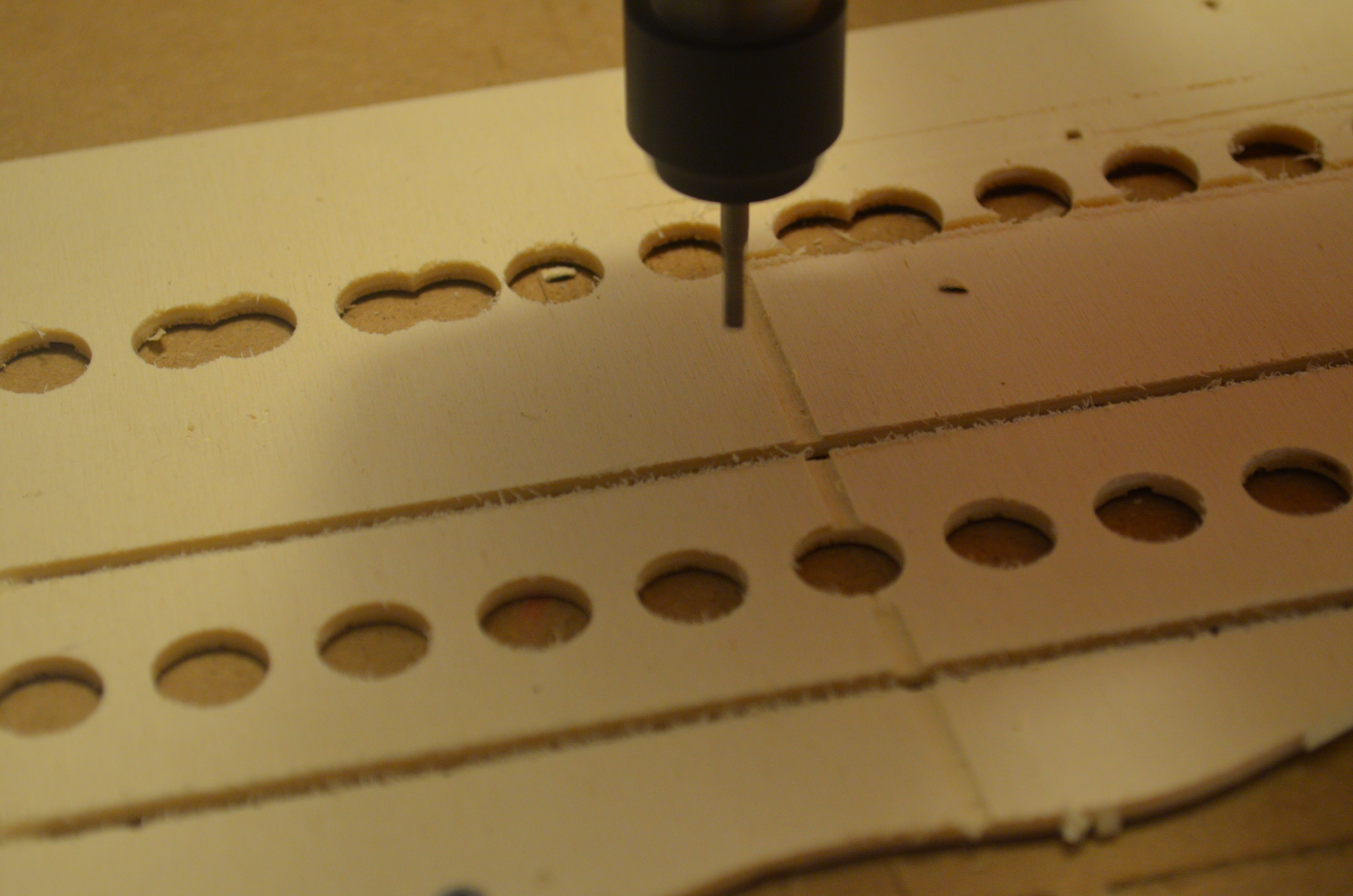
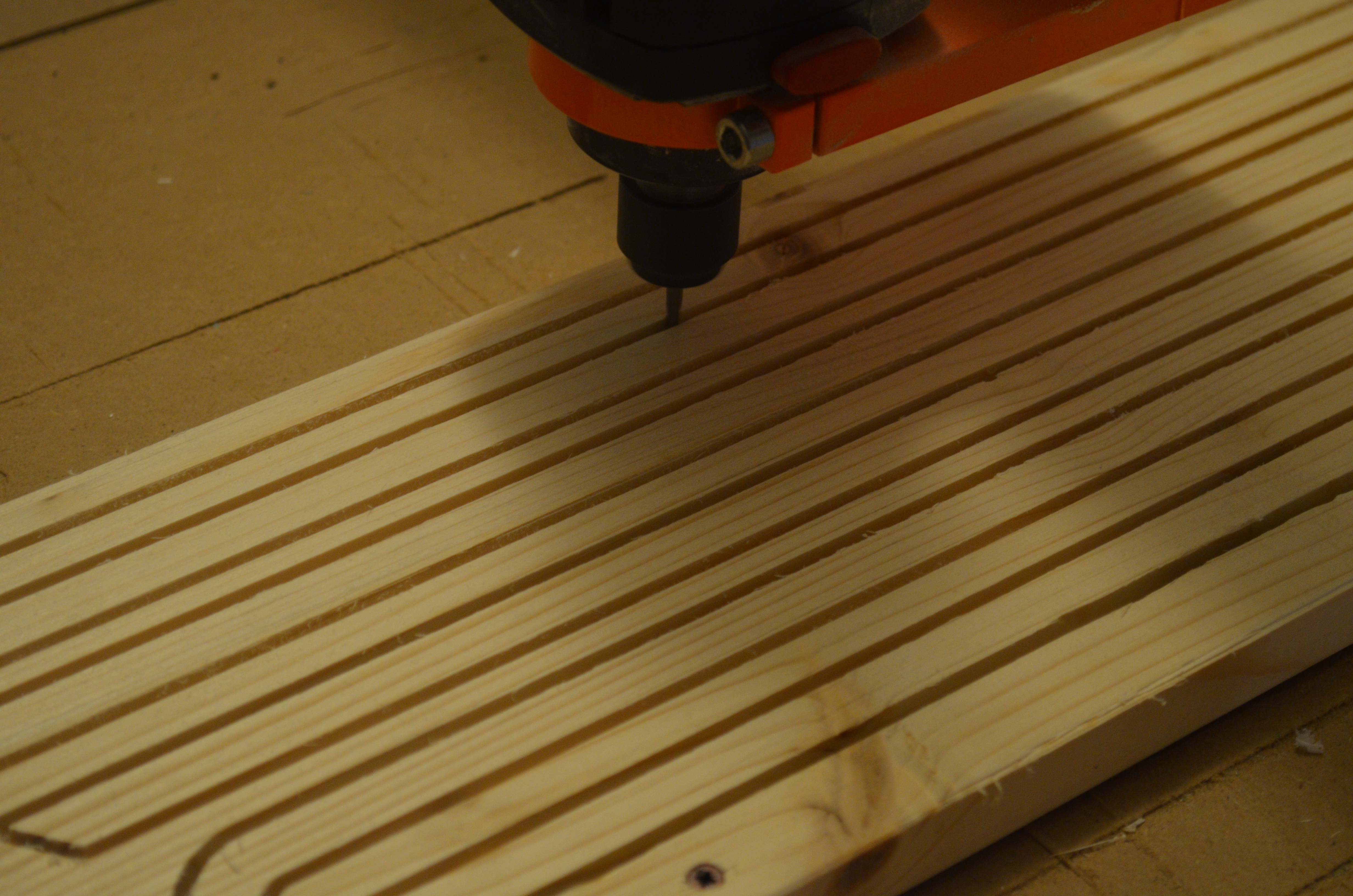
5. From the software, generally provided by the manufacturer, load the G-Code file corresponding to the first milling job you want to perform. Remember that, if your G-Code contains both engraving tasks and cutting tasks, it is better to start with the engraving. Turn on the spindle carefully and then start the milling operation from the software interface on your computer.
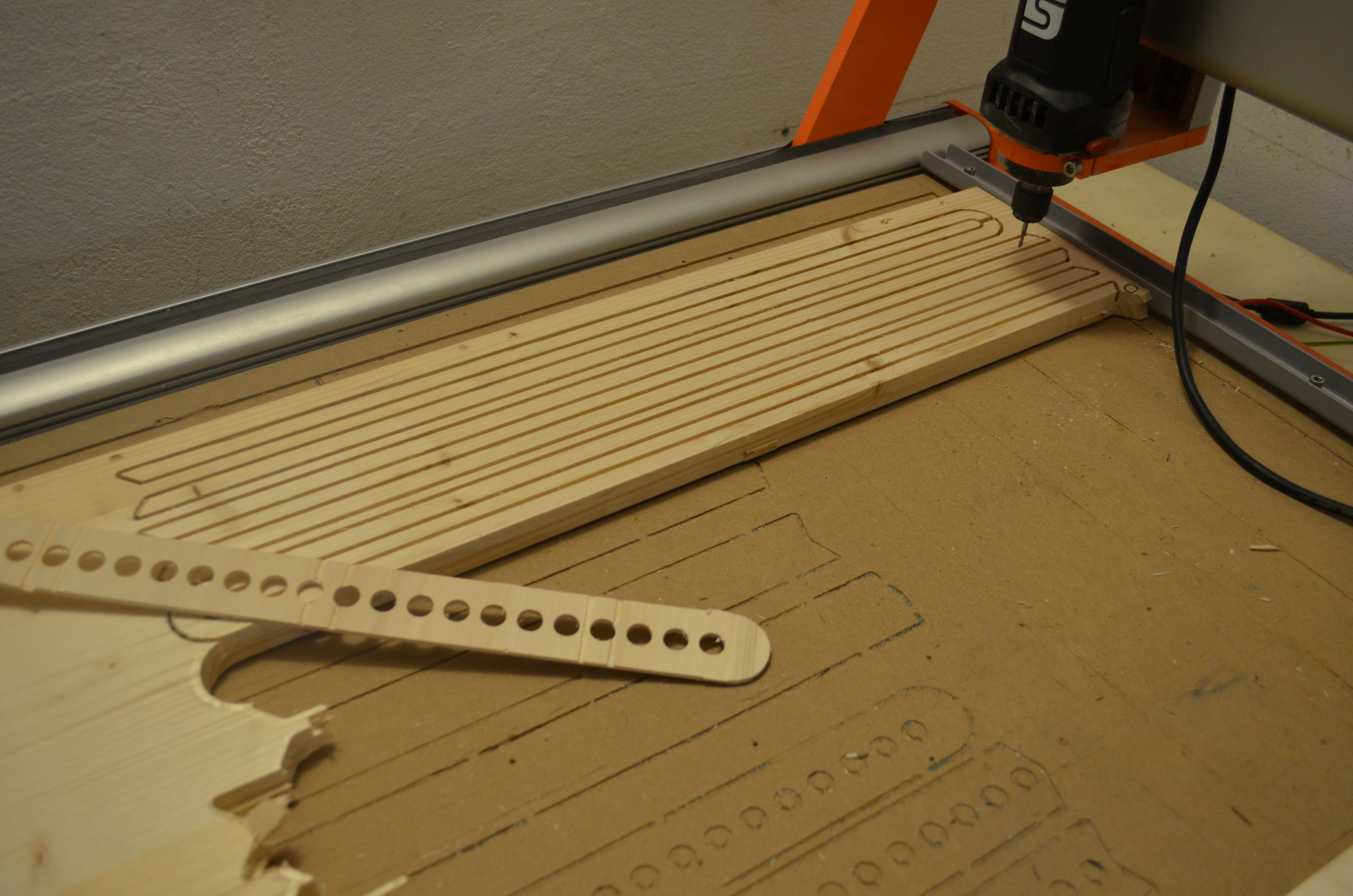
6. Wait for the first job to finish and repeat the operation for the other milling jobs required, adjusting the XYZ positioning of the spindle accordingly and changing the milling tool as needed between jobs.
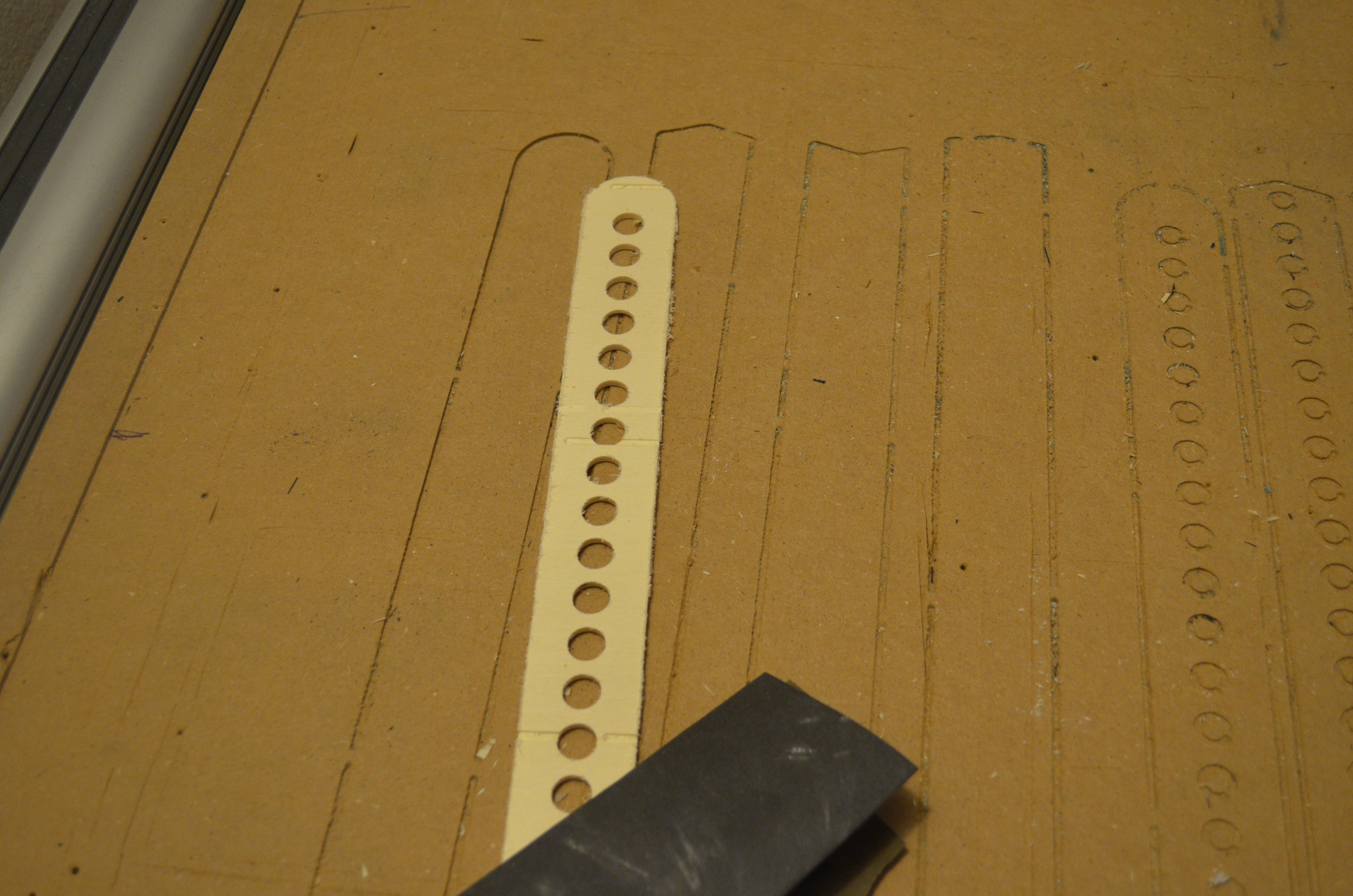
7. When all the milling operations are completed, you can remove the milled shapes from the original material. Because of the tabs that kept it in place during the milling, you will likely need the help of a chisel for this task. In this phase, you might also notice that, due to irregularities in the material’s thickness, in some places the shape might not have been cut thoroughly. In this case, you can easily use a cutter.
8. As a last step, you should sand the pieces to make them smooth. This is both to make sure that there aren’t any dangerous chippings and to prepare the pieces for a layer of paint, if you plan to apply any.
The tutorial is included solely to educate on how such machines work. We absolutely don’t advise you to follow this part of the tutorial on your own, unless you have previous experience with operating a CNC milling machine, which comes with some safety concerns and necessary technical setup prior to each operation.</p>
Tool Library, when generating the G-Code. Find the milling tool that corresponds to the values you had picked in FreeCAD and attach it to the spindle firmly. If you don’t pick the right milling tool, then the whole milling operation could be compromised. If your object requires both engraving tasks and cutting tasks, thus two types of jobs and likely two types of milling tools, it is better to start with the engraving first. This because once the piece is cut out from the original material, it is kept in place only by the tabs and so it is less stable. Engraving a material is a high precision task that need as much stability as possible.