Fabrication · 3D Data Map
Part 1.c - The two 3D data layers (3D printing GCode)
Full Video Tutorial
Workflow explanations
1. In FreeCAD, open the .fctd file containing the data grid support layer. Move to the Draft workbench, select the final object and go through Draft > Clone. You will now see a new Clone element in the left sidebar. Do the same for the .fctd file containing the 3D data layer. Create a new FreeCAD project and copy-paste these two Clone elements in the new file.

2. Change view by going through View > Standard Views > Front. From the left side panel, select the Clone element representing the 3D data layer. Navigate to the Data menu at the bottom of the left panel sidebar. Go to the Placement > Position > Z and increase/decrease the value until its sits right below the data grid support layer (in our case, we had to use a value of -20.5 mm).

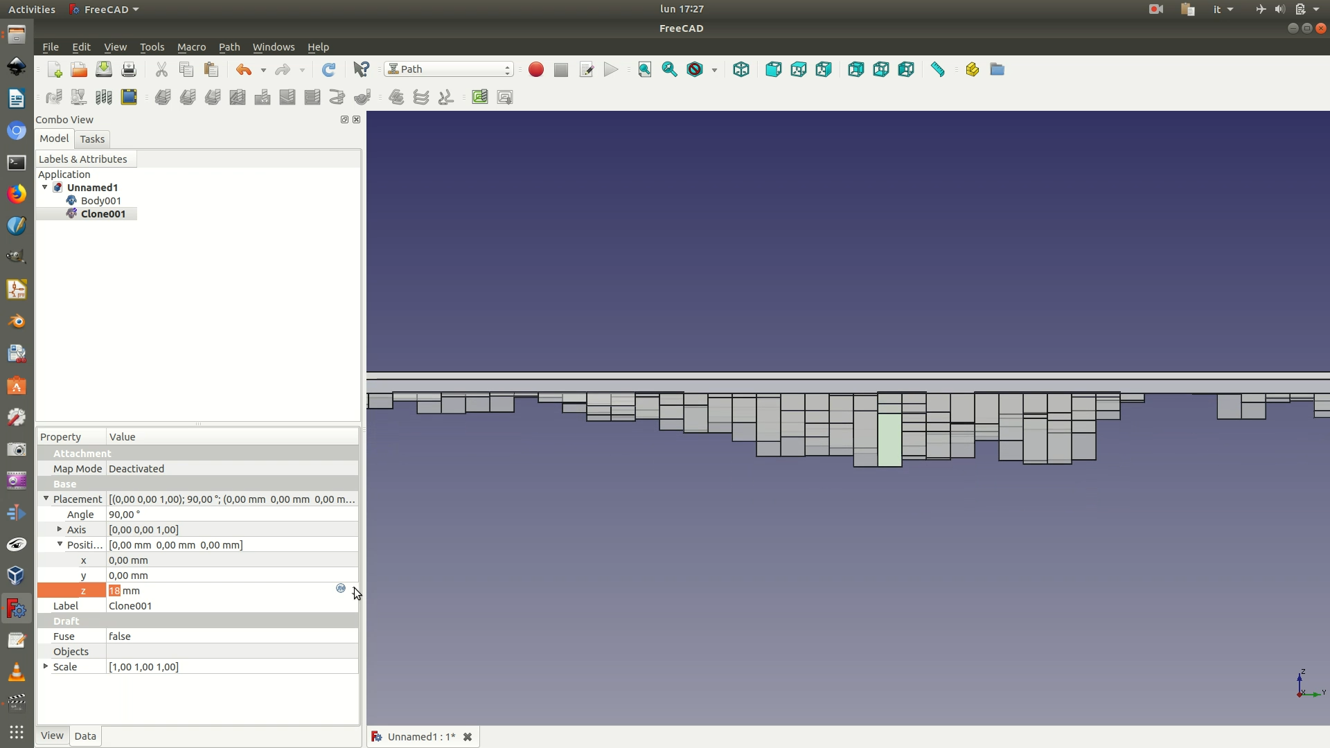
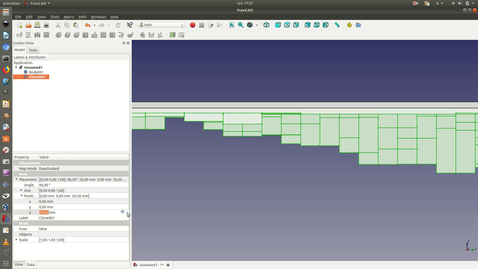
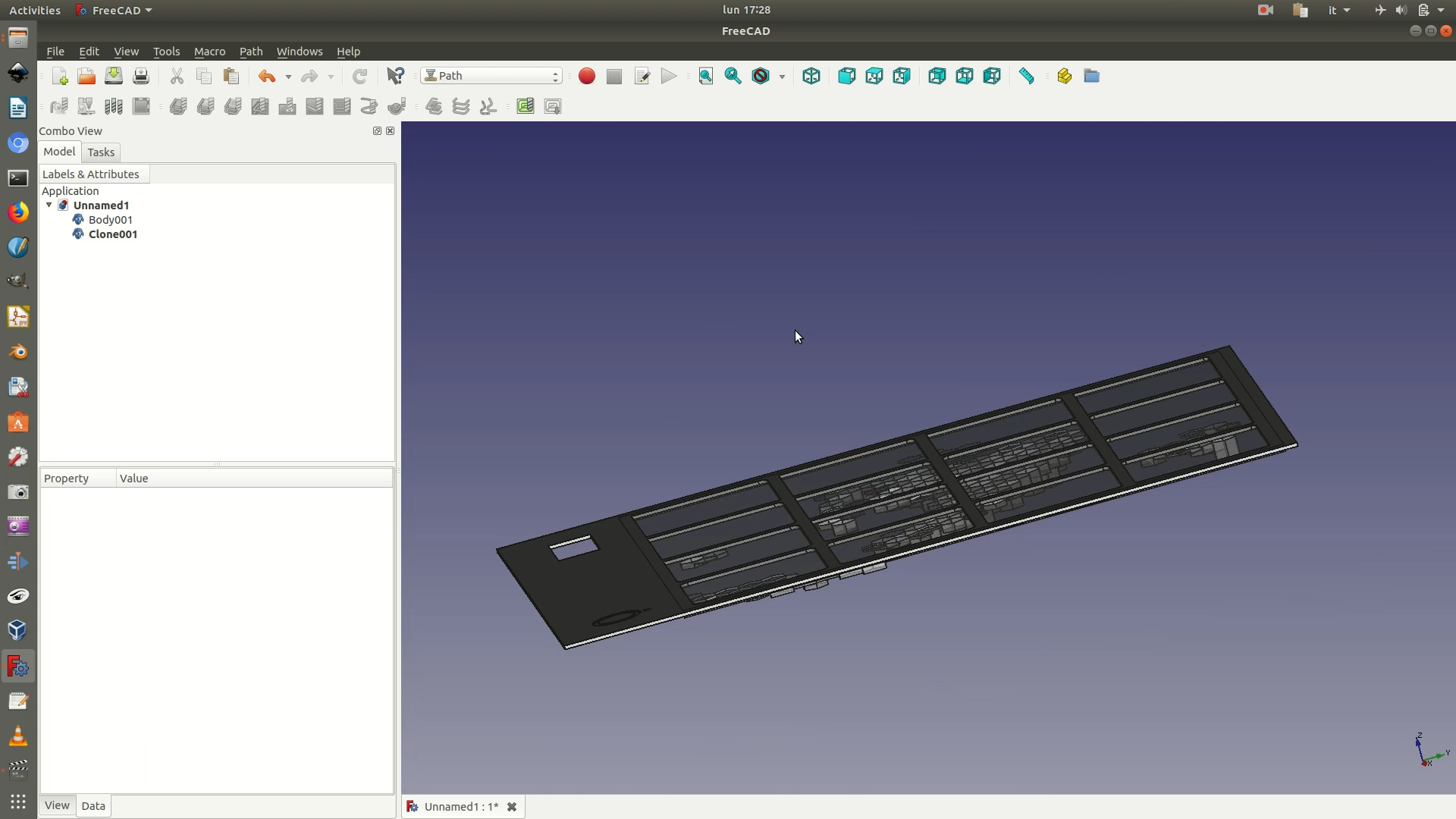
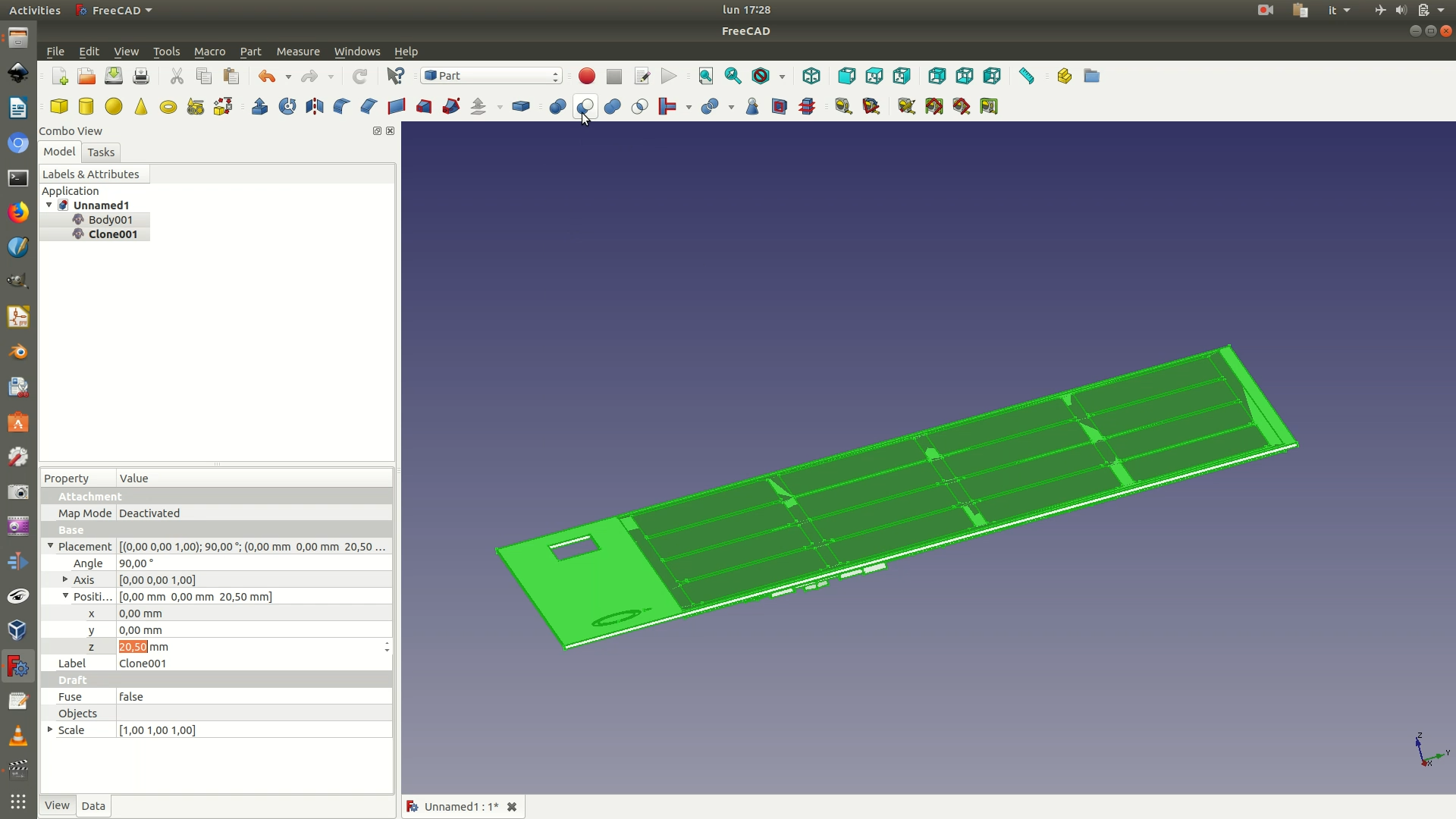
3. Move to the Part workbench. Select both the Clone element of the 3D data and the Clone element of the support grid (in this order!) and go through Part > Boolean > Cut. The result will be a new Cut element, consisting of the 3D data layer with the grid pattern of the support layer cut into it.
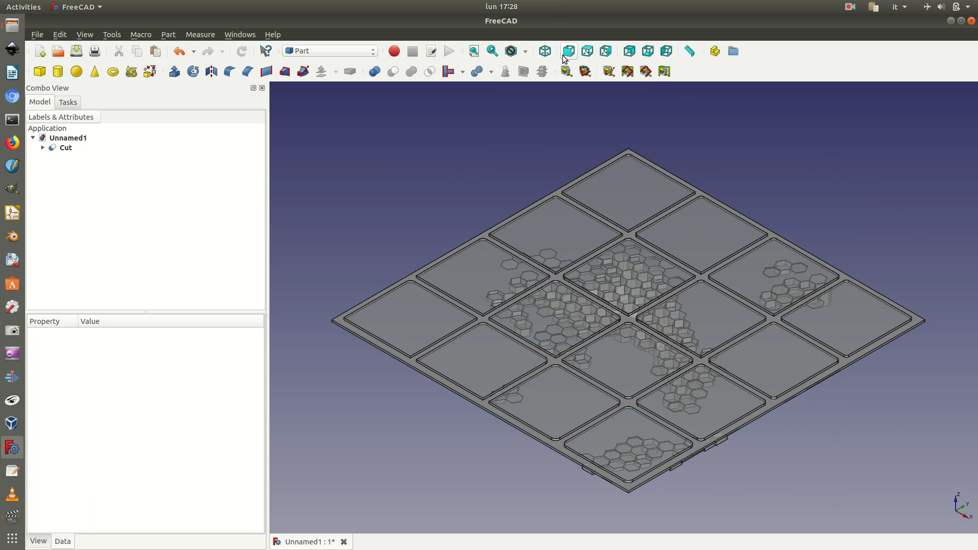
4. Move to the Part Design workbench. Select the Cut</code> element and click on Part Design > New body. This will create a new container Body element that uses the selected Cut element as base. Click on the face of the object shown in the second image below. Then go through the menu Part Design > New Sketch. This will create a new sketch on top of the face you had selected.
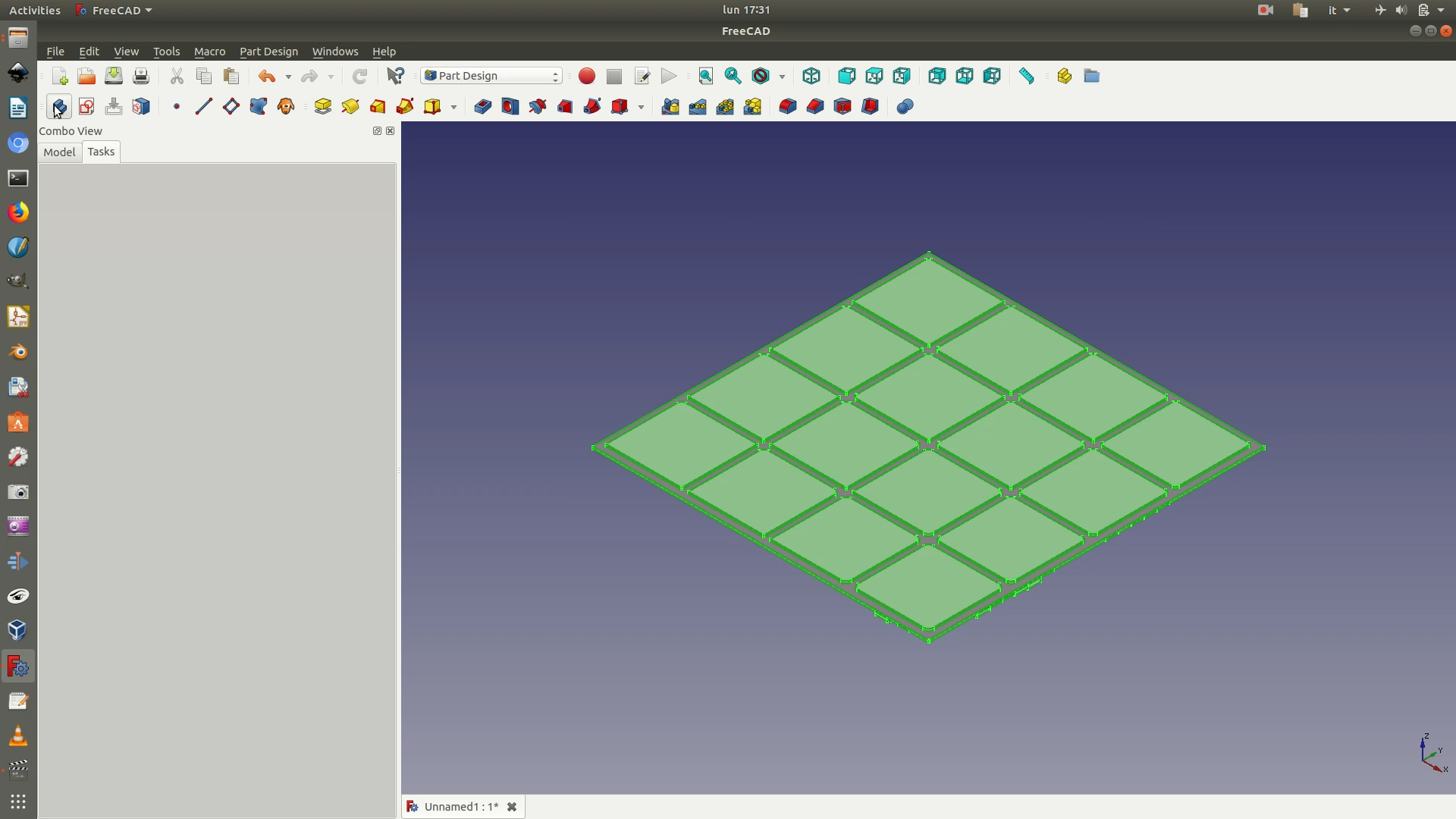
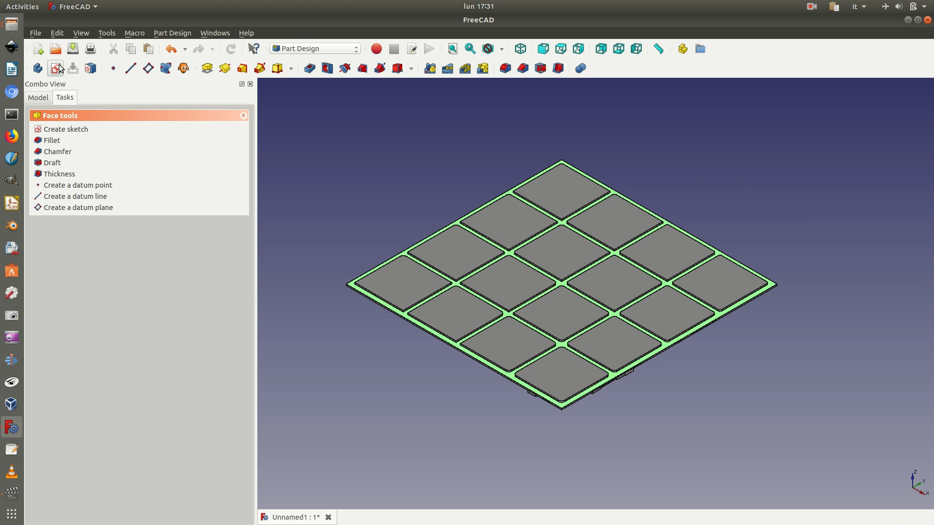
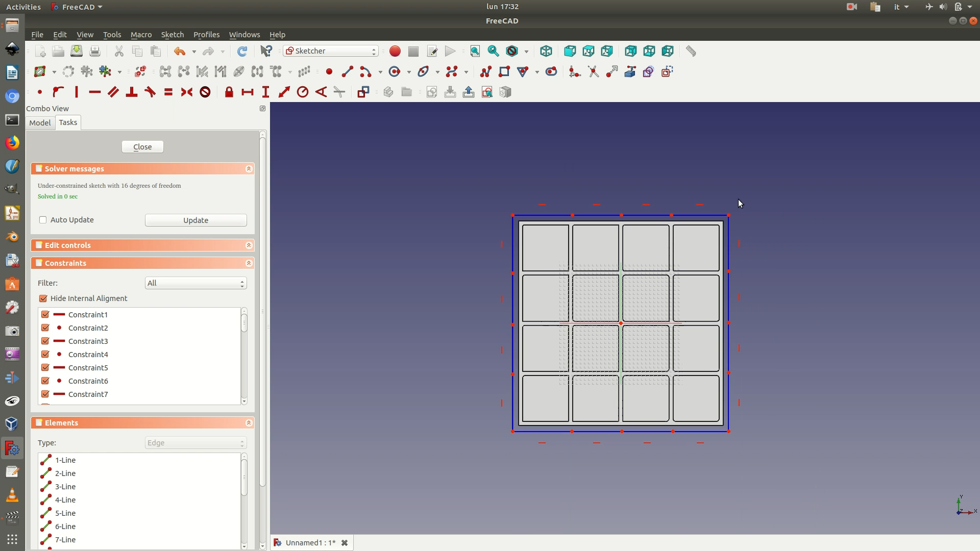
5. Toggle to Construction Mode. Construction Mode allows you to draw lines that are not actually part of the object itself, but that only serve as modeling supports. To switch to Construction Mode, go through the menu Sketch > Sketcher Geometries > Toggle Construction Geometry. Everything you draw now will be blue to indicate that the Construction Mode has been activated. Now navigate through Sketch > Sketcher geometries > Create polyline. Draw a series of horizontal and vertical segments like in the image below, 4 four segments for each side of the square data layer.
6. Go through the menu Sketch > Sketcher geometries > External geometry. Then click on the top and bottom segments of the square base of the 3D data layer to select them (see image below). This will import the selected segments as guidelines in the sketch.
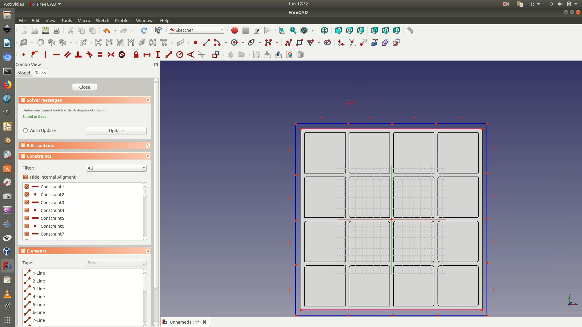
7. Click on the top right vertex of the constructed square and on the top right vertex of the square base (see image below). Make them coincidental by going through Sketch > Sketcher constraints > Constrain coincident. Repeat for the other vertices of the squares until the blue segments drawn in construction mode are coincidental with the edges of the square data layer.
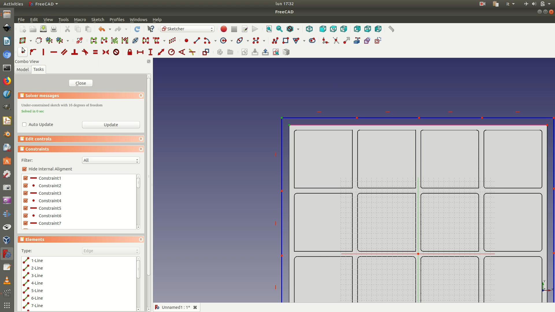
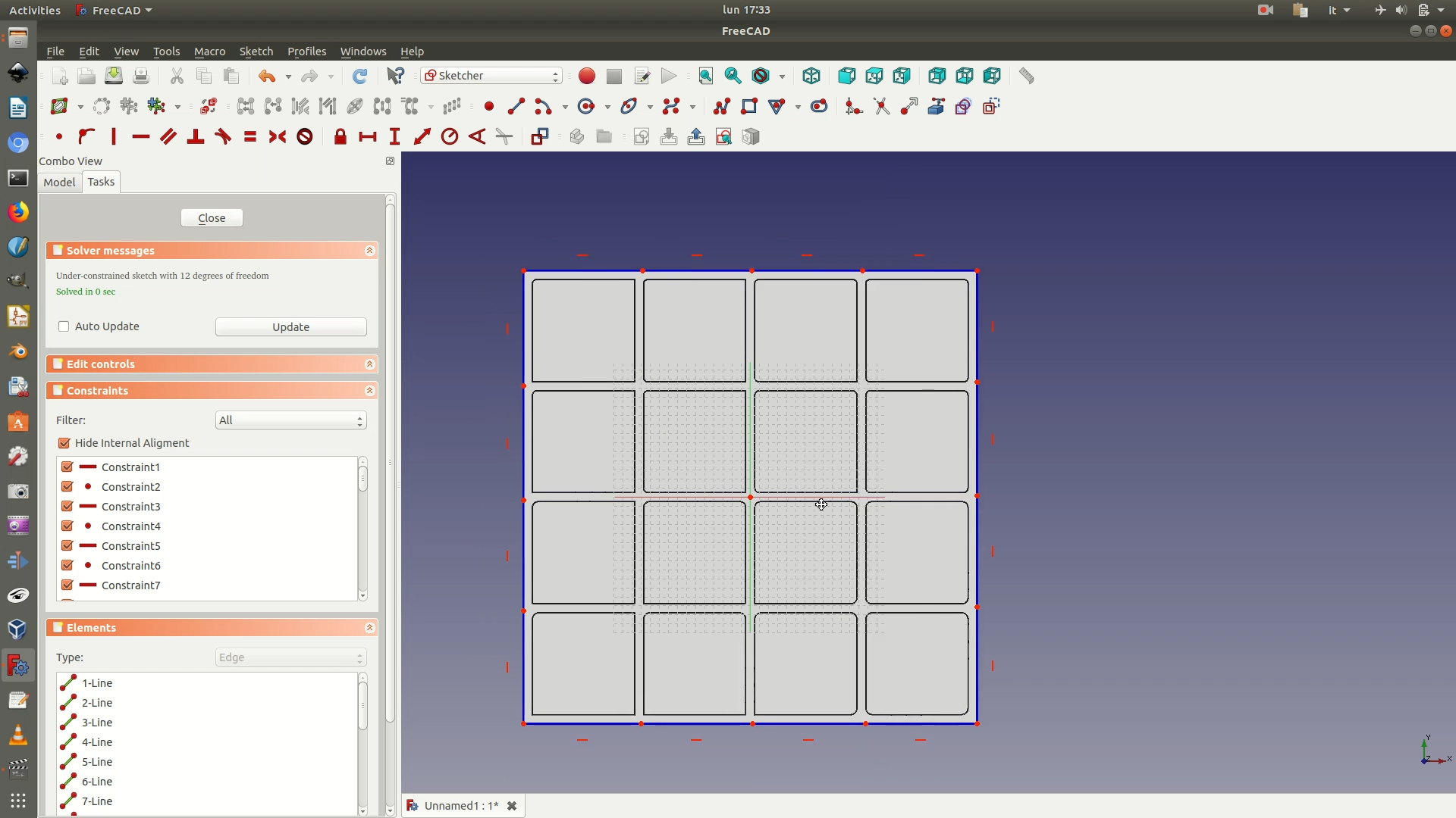
8. Navigate again through Sketch > Sketcher geometries > Create polyline. Draw a series of horizontal and vertical segments like in the image below, so that the end result is a grid pattern of squares similar to those of the data layer, covering half of the data layer. (For the other half, we’ll mirror this pattern to save time).
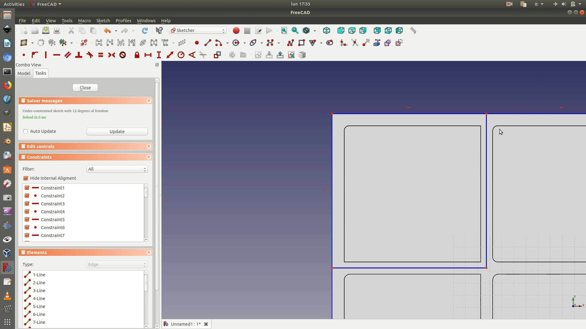
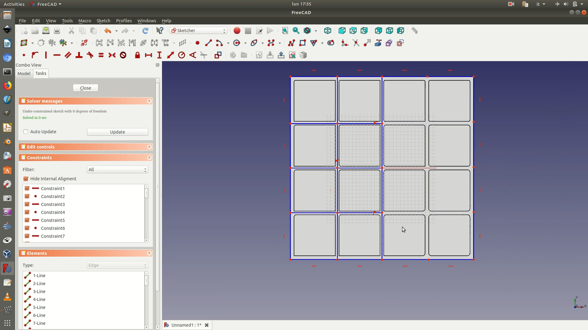
9. Navigate through Sketch > Sketcher geometries > Create polyline and draw the two diagonal lines shown in the first image below. Select these two diagonal lines and make them of equal length by applying the Equality Constraint (Sketch > Sketcher constraints > Constrain equal) (see second image below). Repeat this operation for all the blue squares (See last image below: small red equal signs are next to all the blue diagonal lines)
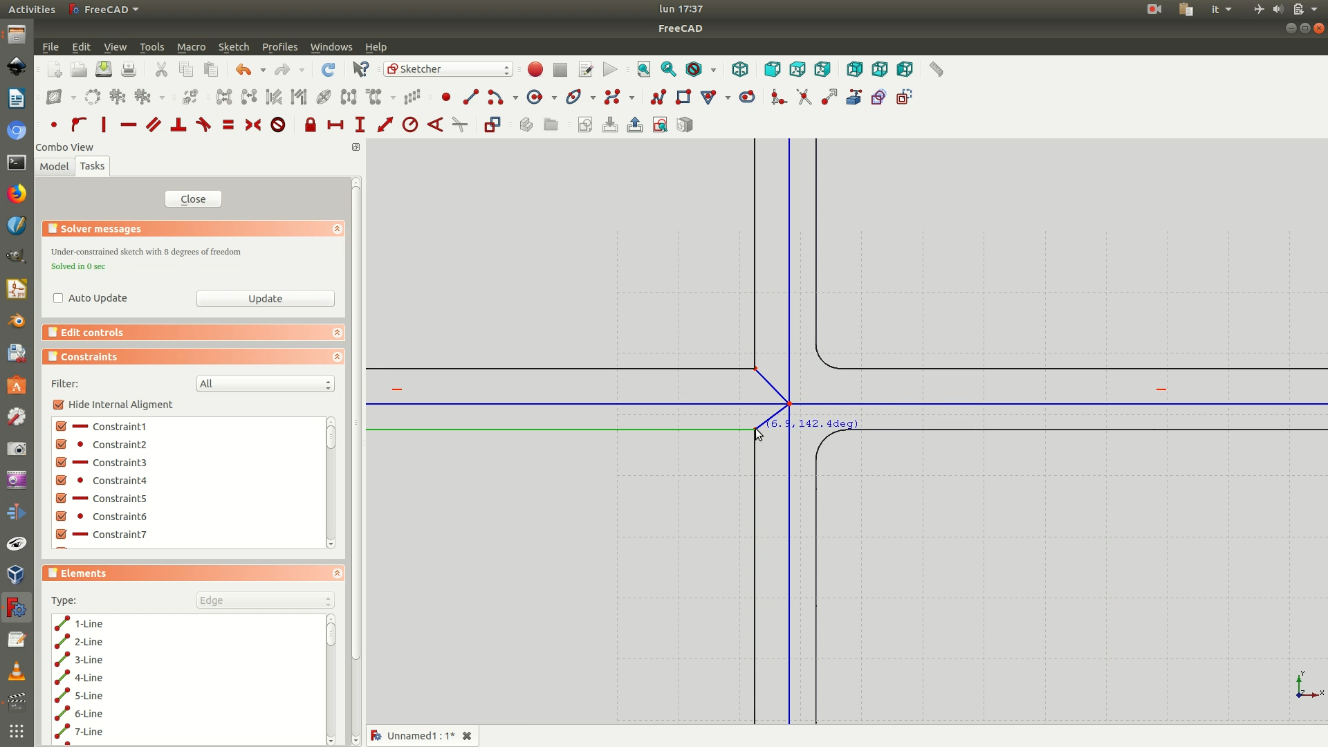
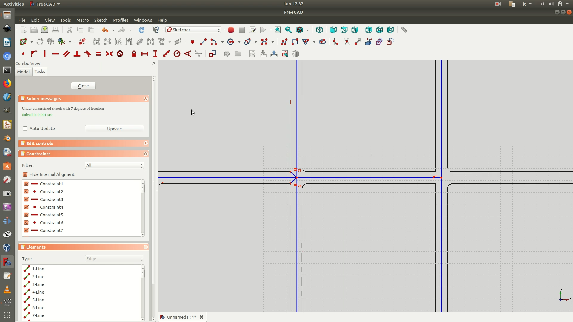
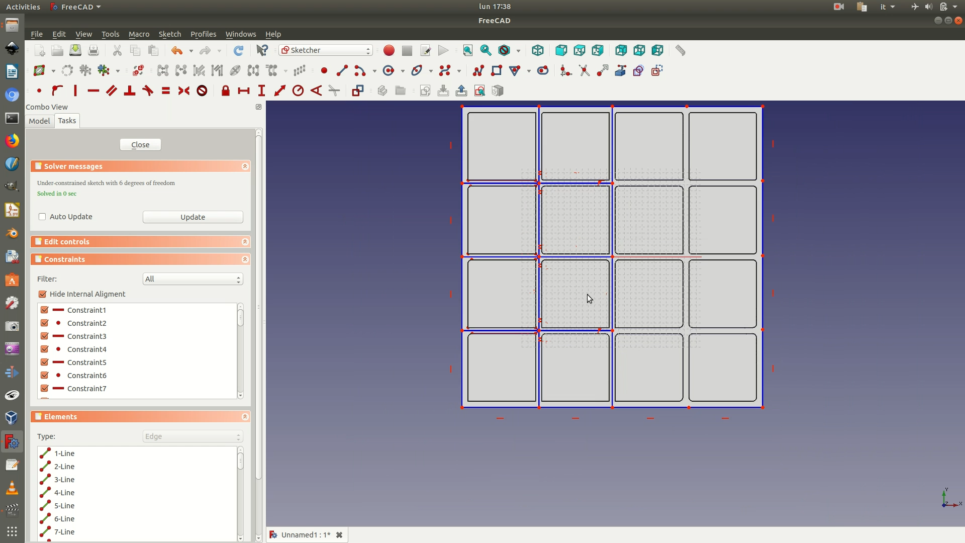
10. Select the 4 blue construction lines that make up the first square (see image below). Click on Toggle Construction Mode. This will convert the selected lines from blue construction lines to white sketched lines. Now close the sketch.
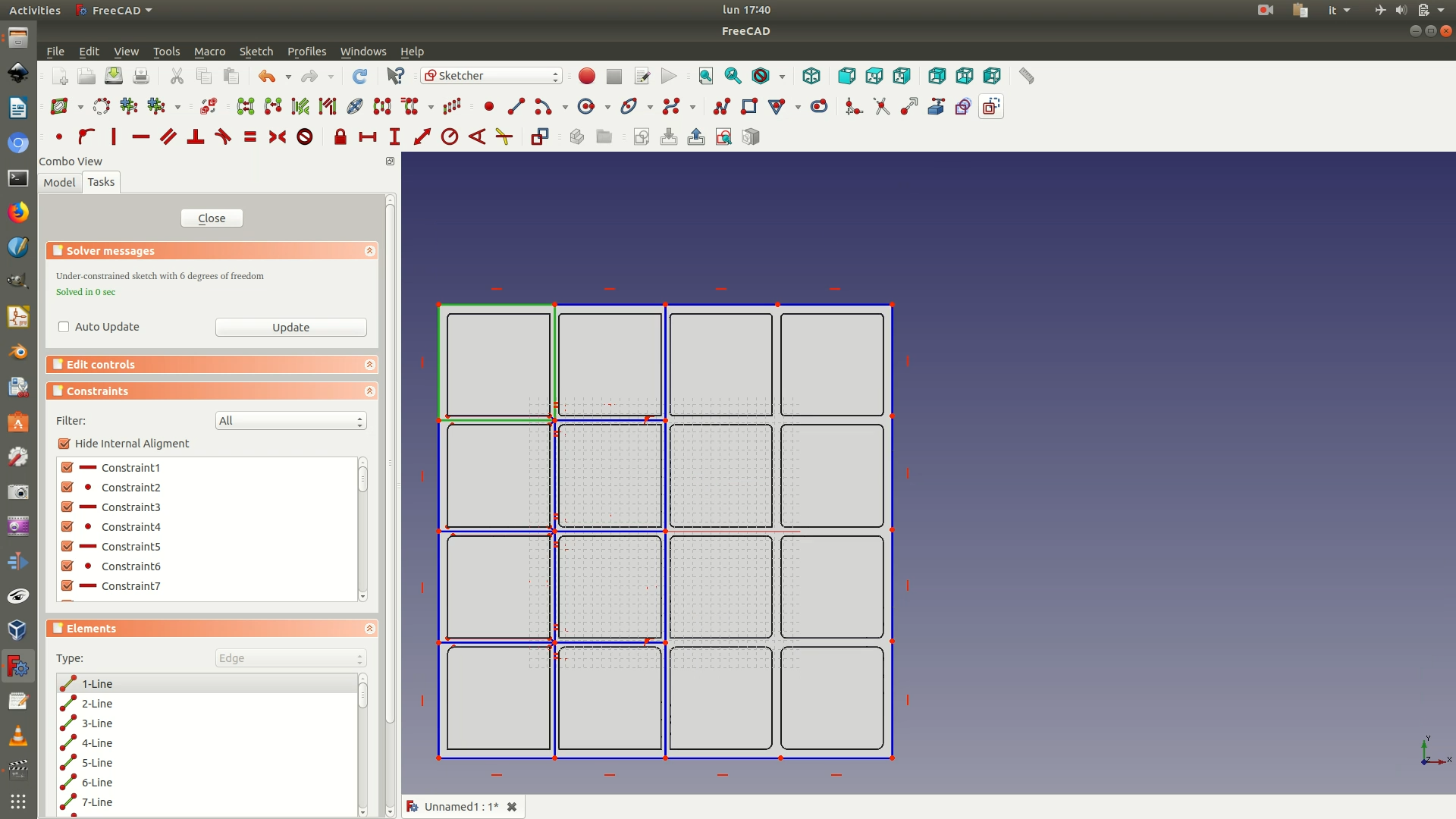
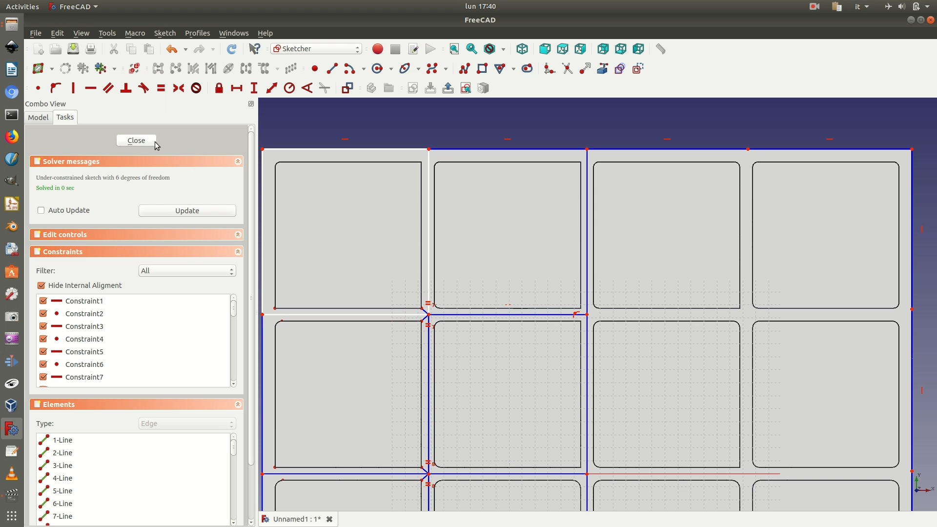
11. Switch to the Part workbench. From the left sidebar, select the sketch and go to Part > Extrude. In the selection panel that has appeared on the left, set the following parameters:
Length > Along > 50 mmSymmetric: checkbox checked
Click OK. Depending on your machines, it might take a few seconds, but at the end of the processing you will see a 3D block corresponding to the first section of the data you will 3D print.
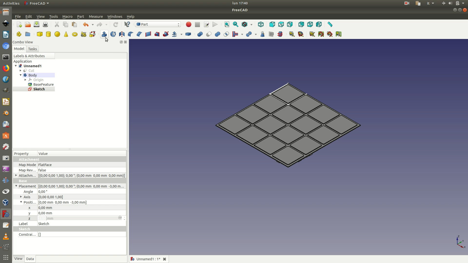
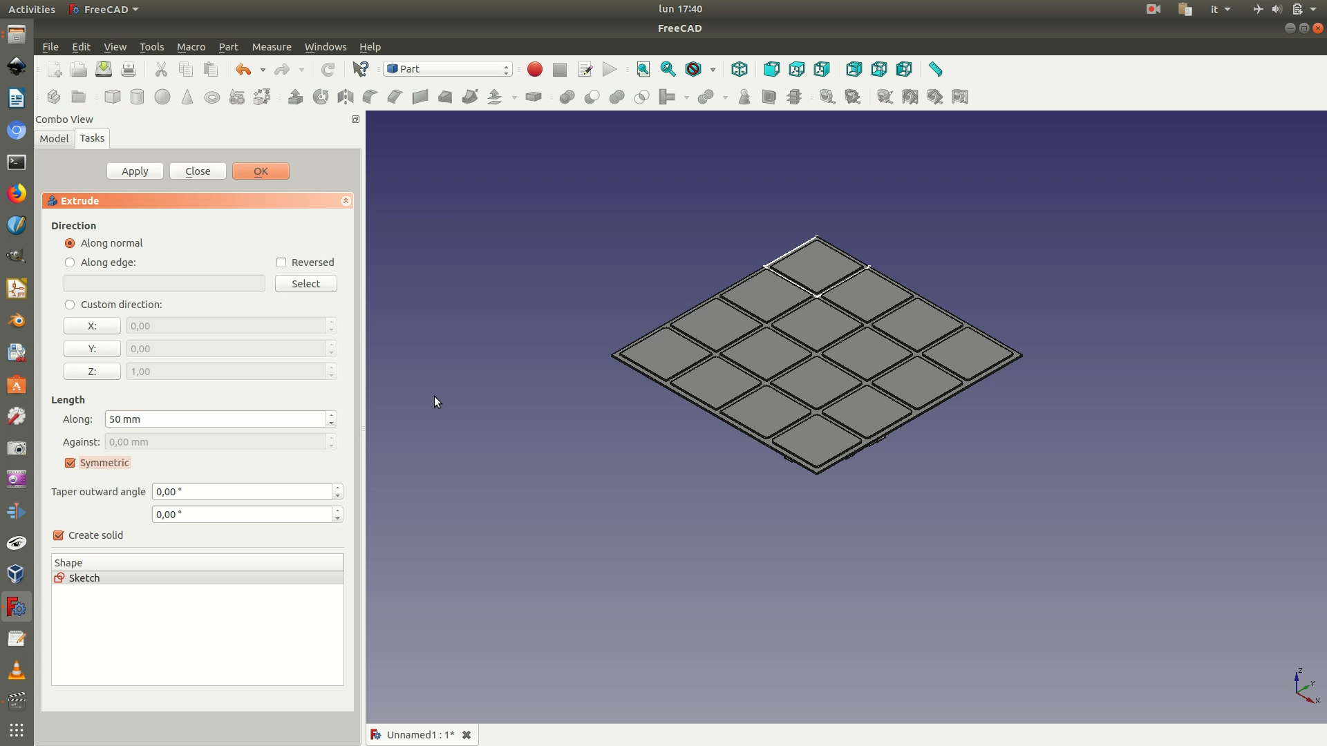
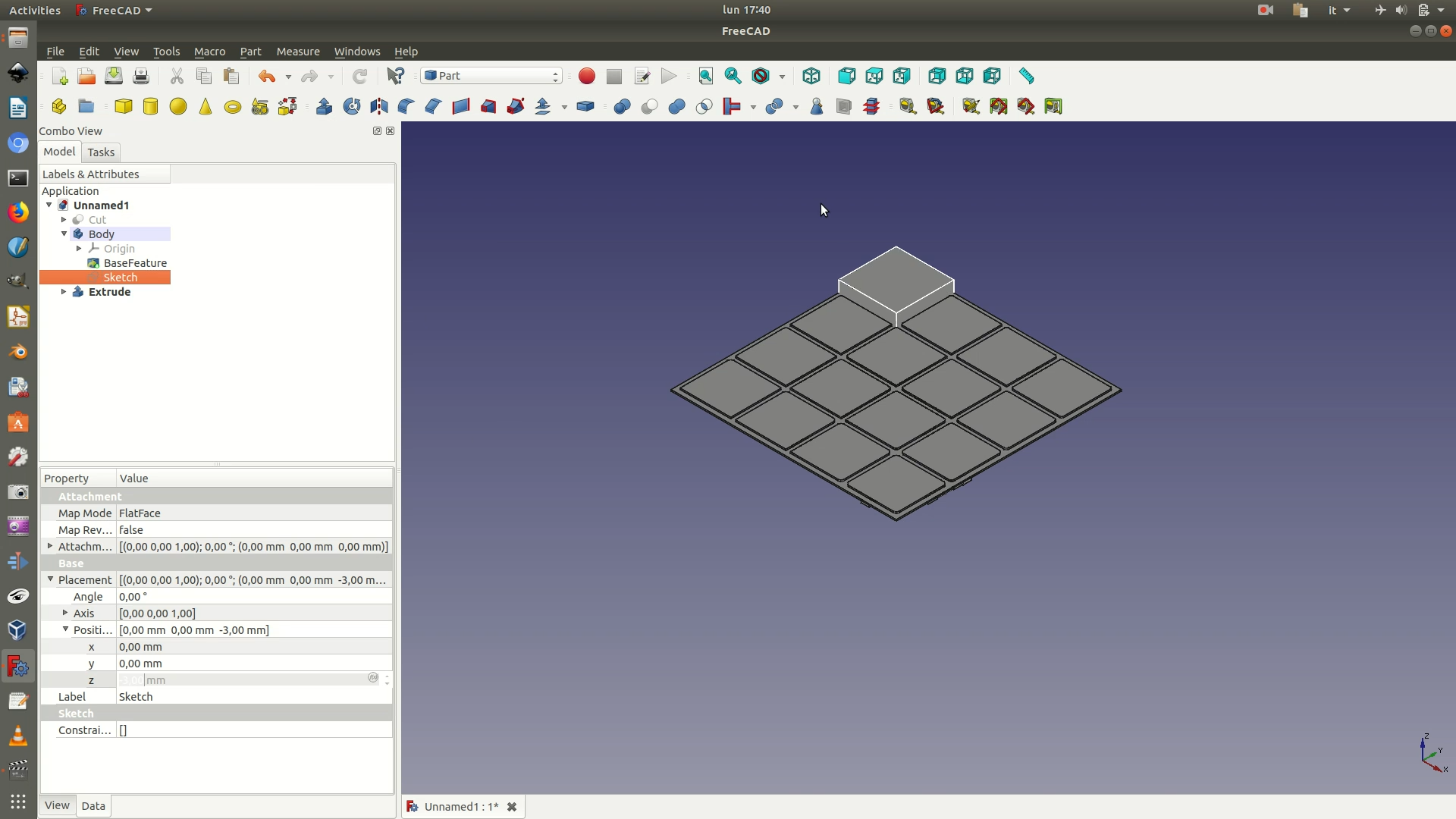
12. Select the 3D block, which is the last Extrude element on the left sidebar. Navigate through Part > Mirroring. On the Mirroring pane that appears on the left, select XZ as plane and click OK. You will now have a second extruded block at the bottom.
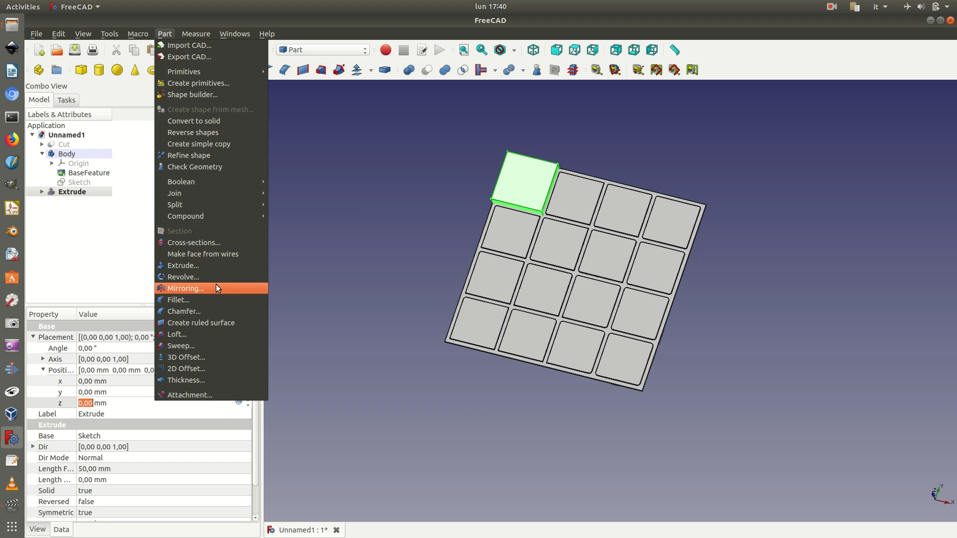
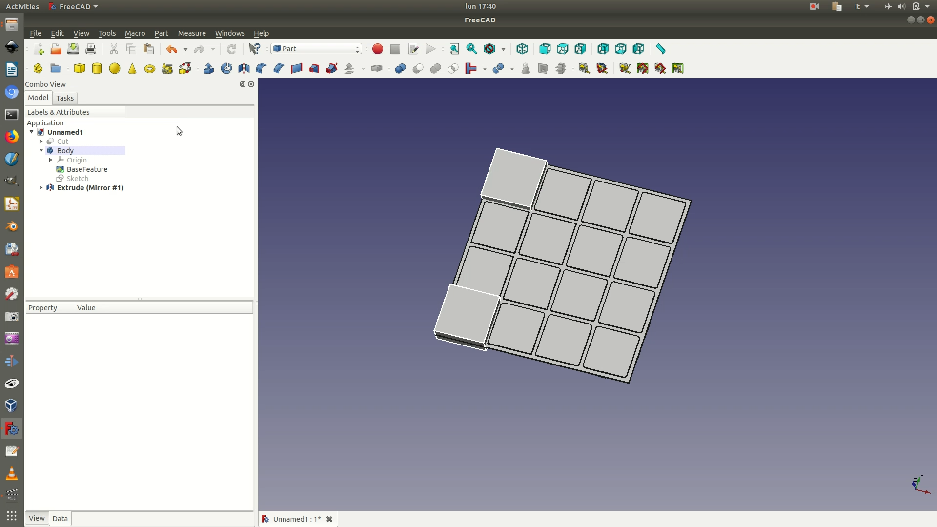
13. Now select the first and second blocks (on the left sidebar, the Extrude element and Extrude (Mirror #1) element). Navigate through Part > Mirroring. On the Mirroring pane that appears on the left, select YZ as plane and click OK. You will now have a third and fourth extruded block on the other side.
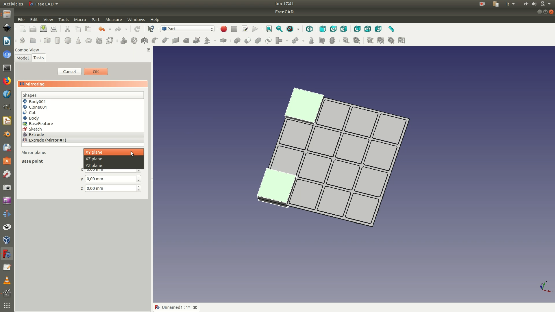
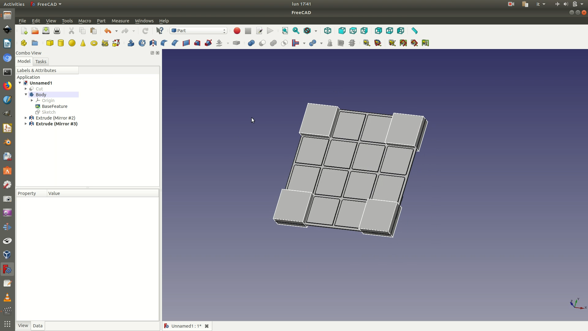
14. From the left sidebar, select the last Body element and copy-paste it. Hide the previous original Body element and the four Extrude elements representing the four 3D blocks. Then, expand the new Body element copy, navigate to the Sketch element contained and double-click to open it.
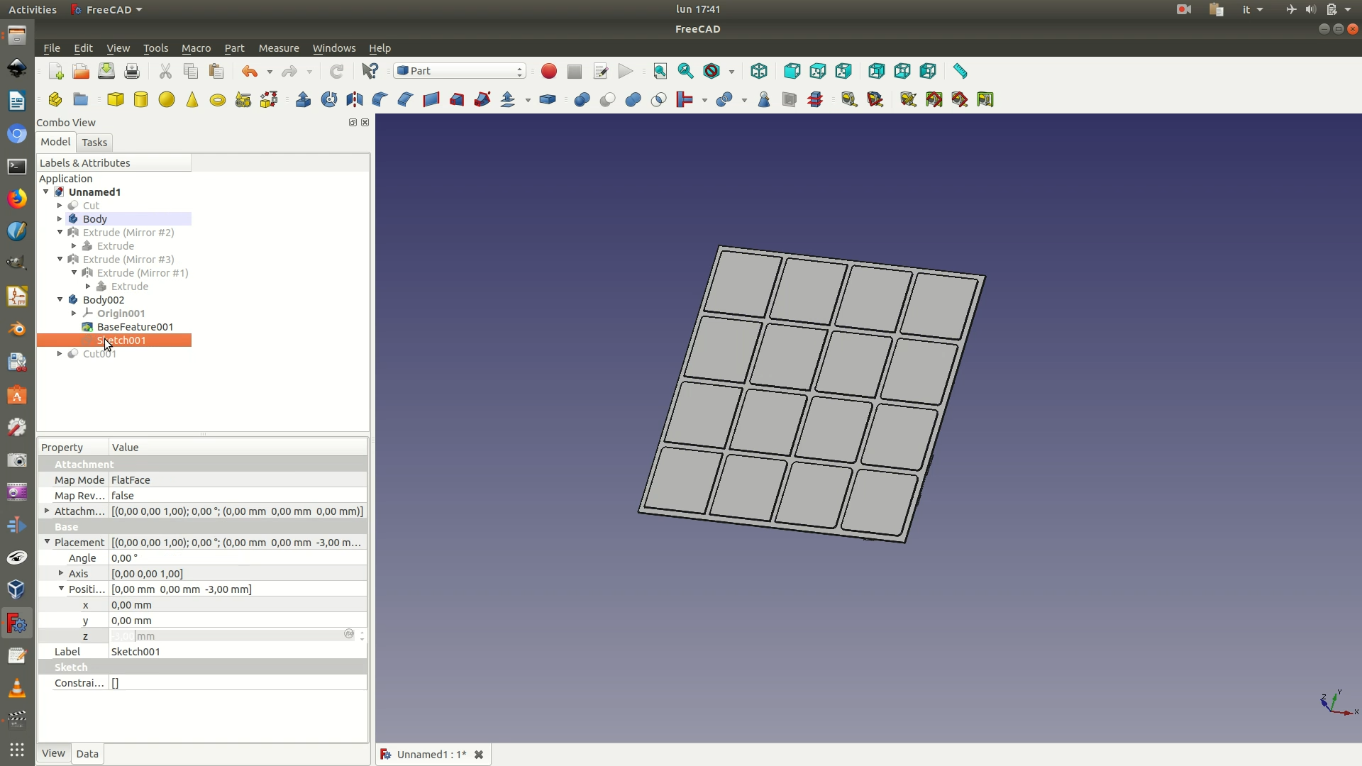
15. Select the three segments of the first square, shown in green in the image below. Go through the menu Sketch > Sketcher Geometries > Toggle Construction Geometry. This will convert the sketched lines back to blue construction lines. Now select the segments that form the square right below this one (see second image below) and again Toggle Construction Geometry to convert these construction lines to sketched lines. Close sketch.
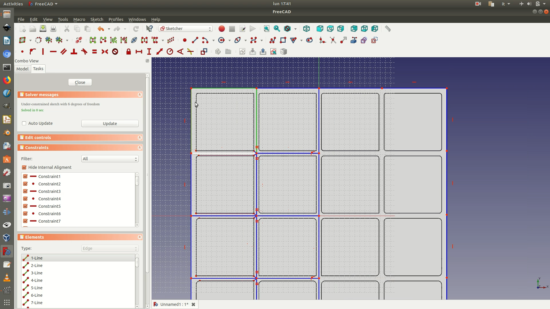
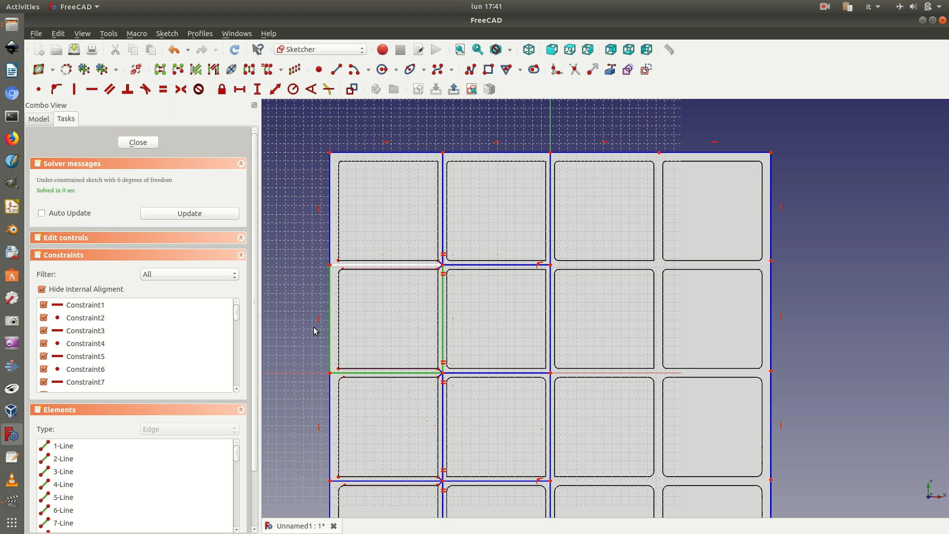
16. Repeat steps 11-13 and you will now have an object like the image below.
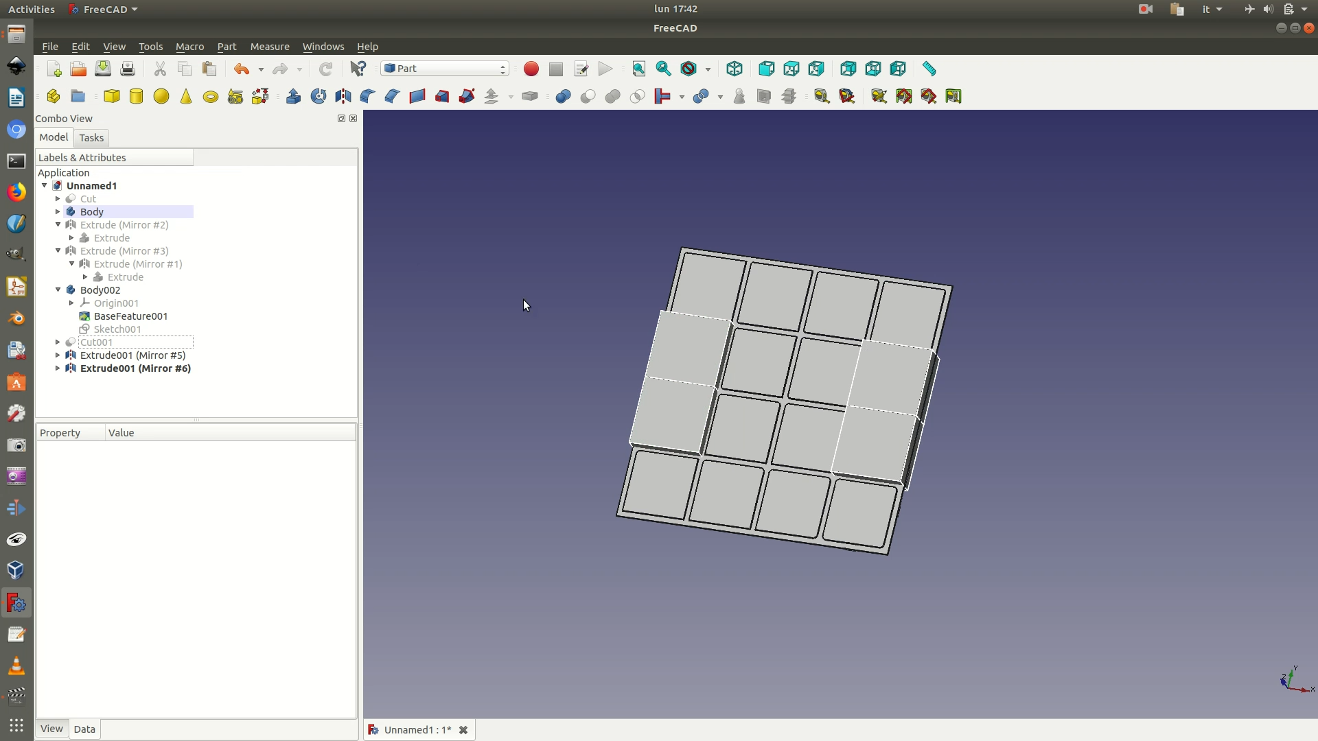
17. From the left sidebar, select the last Body element and copy-paste it. Hide the previous original Body element and the four Extrude elements representing the four 3D blocks. Then, expand the new Body element copy, navigate to the Sketch element contained and double-click to open it.
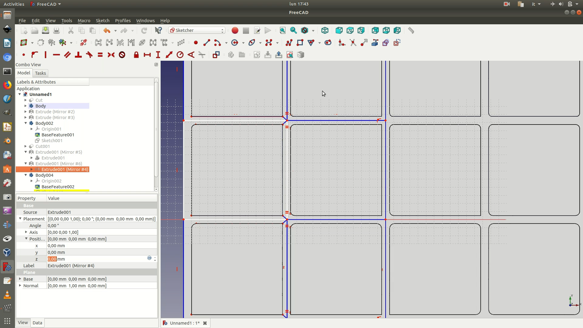
18. Select the three segments white of the second square you’ve worked on, shown in green in the first image below. Go through the menu Sketch > Sketcher Geometries > Toggle Construction Geometry. This will convert the sketched lines back to blue construction lines. Now select the segments that form the square right next to the previous one (see second image below) and again Toggle Construction Geometry to convert these construction lines to sketched lines. Close sketch.
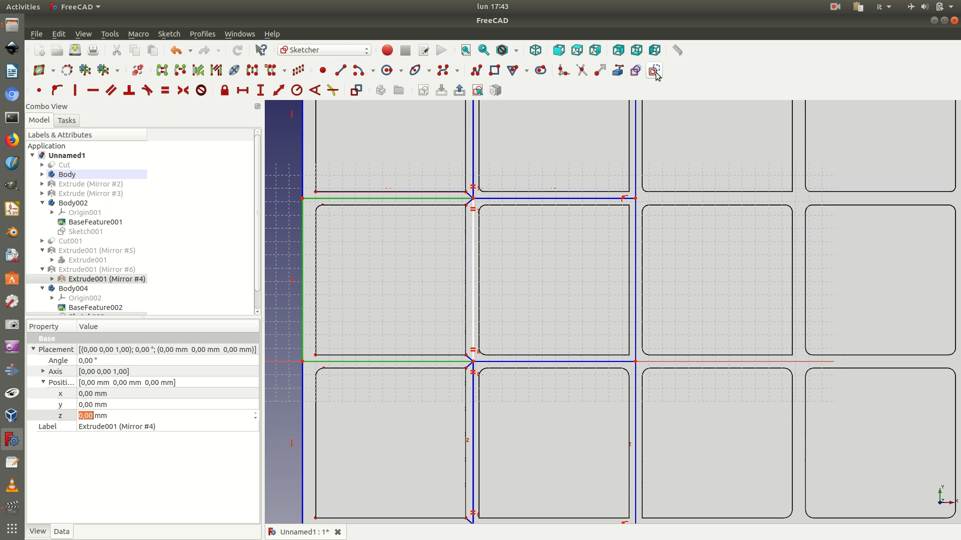
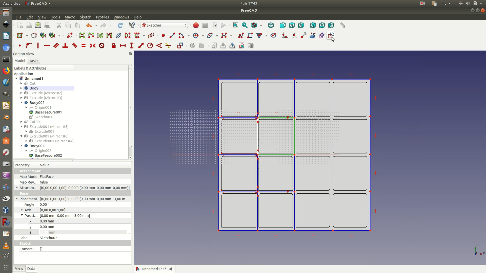
19. Repeat steps 11-13 and you will now have an object like the image below.
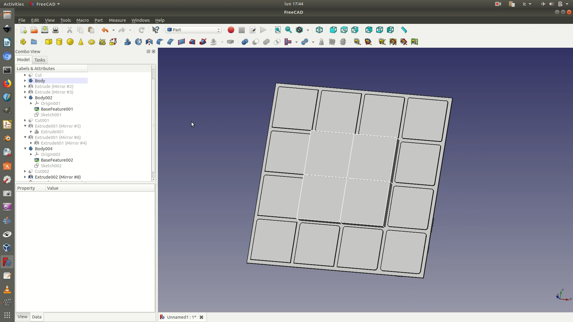
20. From the left sidebar, select the last Body element and copy-paste it. Hide the previous original Body element and the four Extrude elements representing the four 3D blocks. Then, expand the new Body element copy, navigate to the Sketch element contained and double-click to open it.
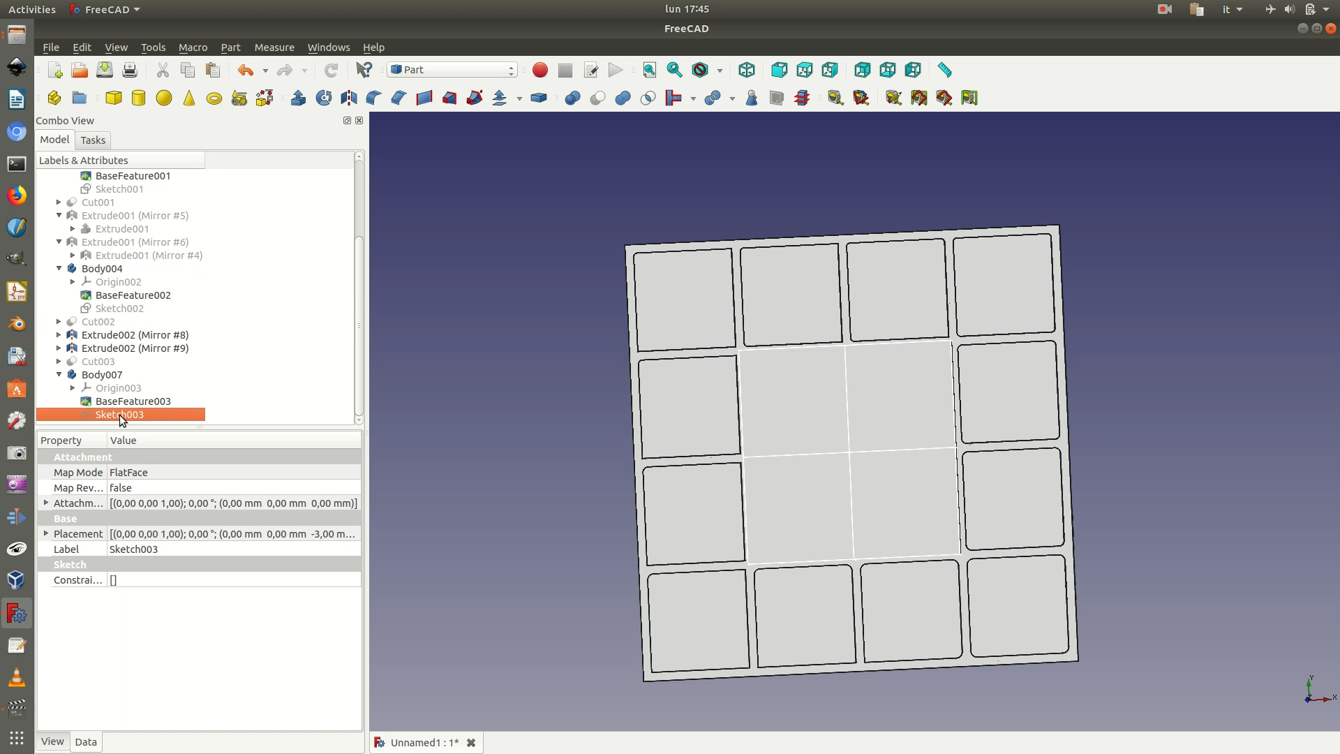
21. Select the three segments white of the third square you’ve worked on, shown in green in the first image below. Go through the menu Sketch > Sketcher Geometries > Toggle Construction Geometry. This will convert the sketched lines back to blue construction lines. Now select the segments that form the square right on top of the previous one (see second image below) and again Toggle Construction Geometry to convert these construction lines to sketched lines. Close sketch.
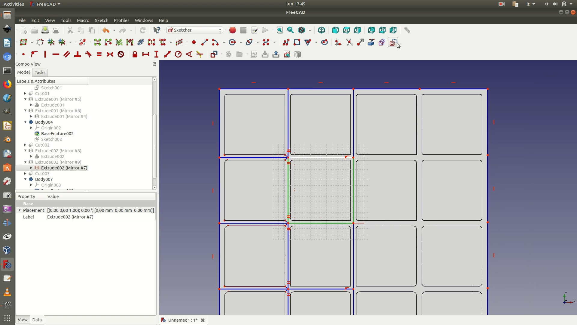
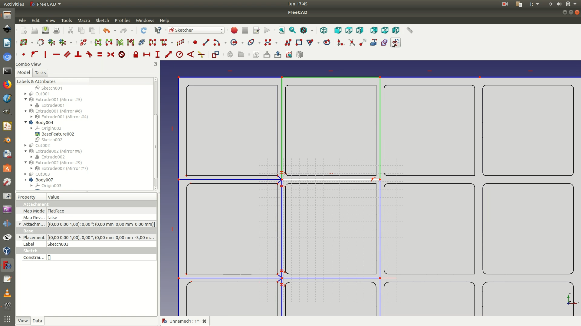
22. Repeat steps 11-13 and you will now have an object like the image below.
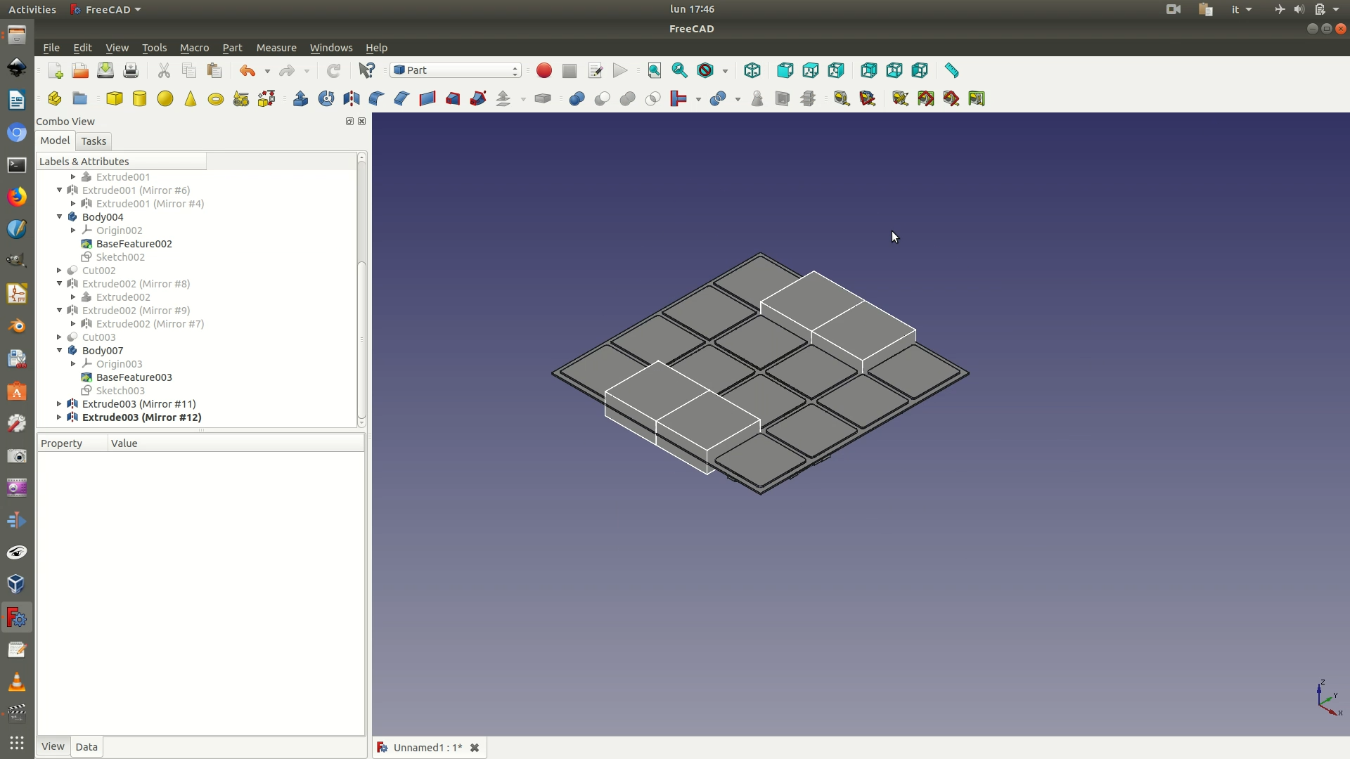
23. From the left sidebar, unhide all the Extrude elements you had previously hidden.
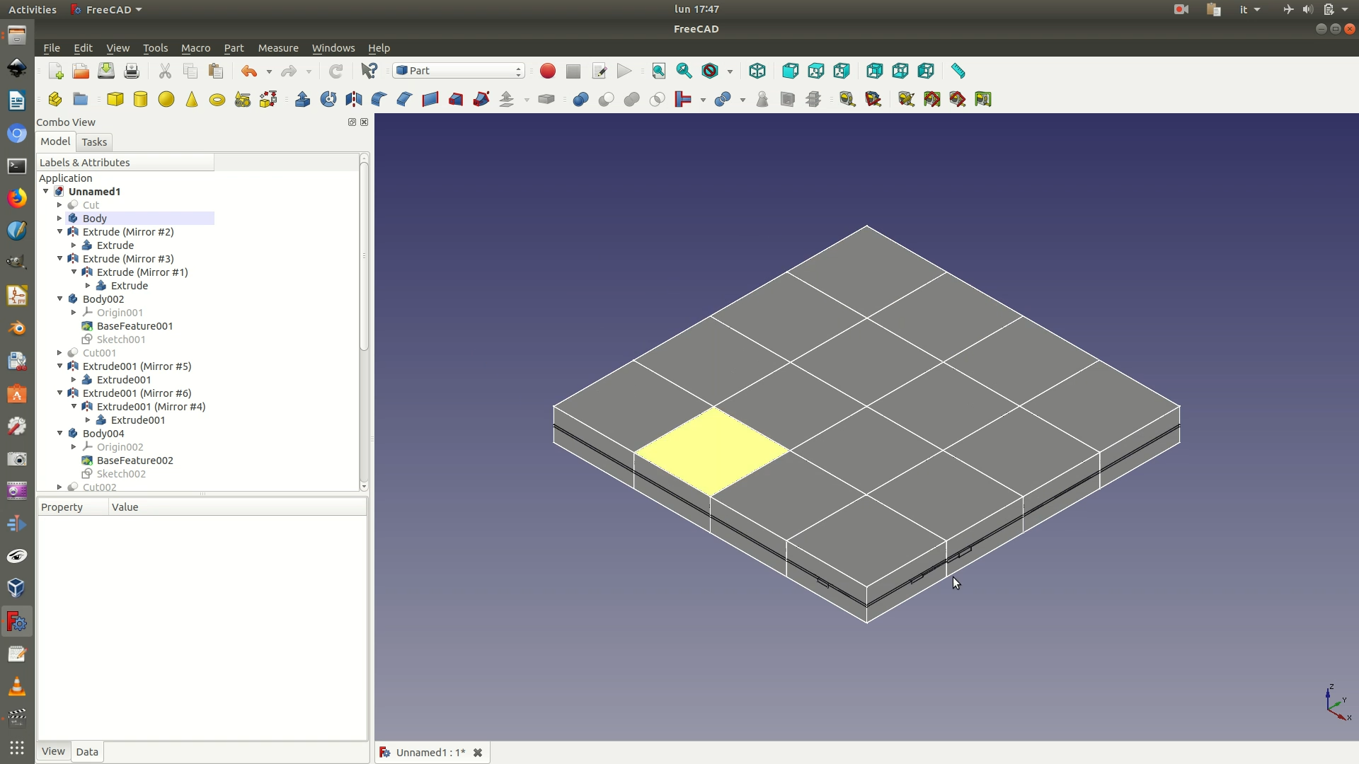
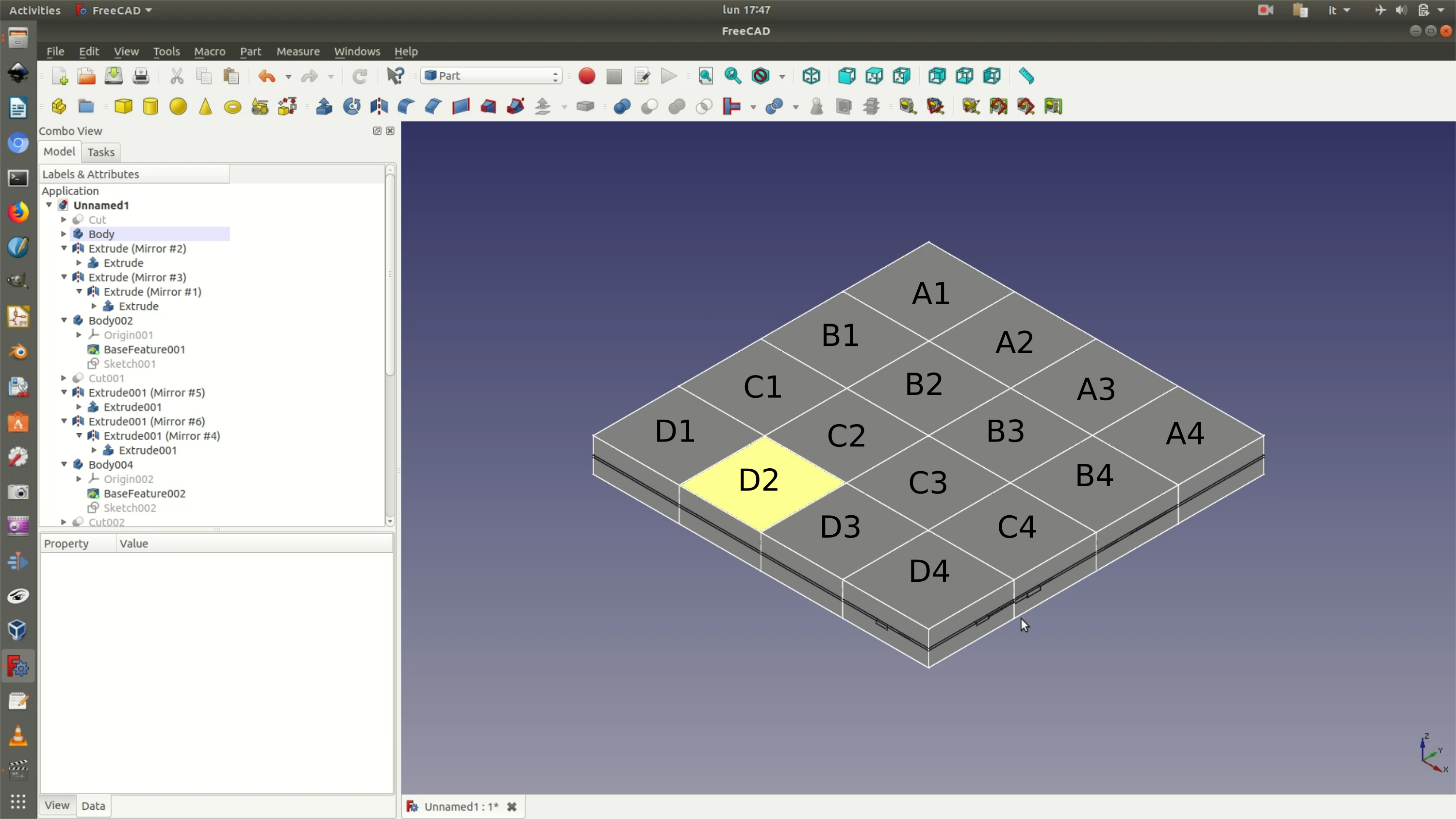
24. In order to make it easier to proceed with the following steps, you should rename each of the 16 3D blocks with a unique id. To rename a block, select the Extrude element and right-click. The following image shows the naming convention used in this tutorial.
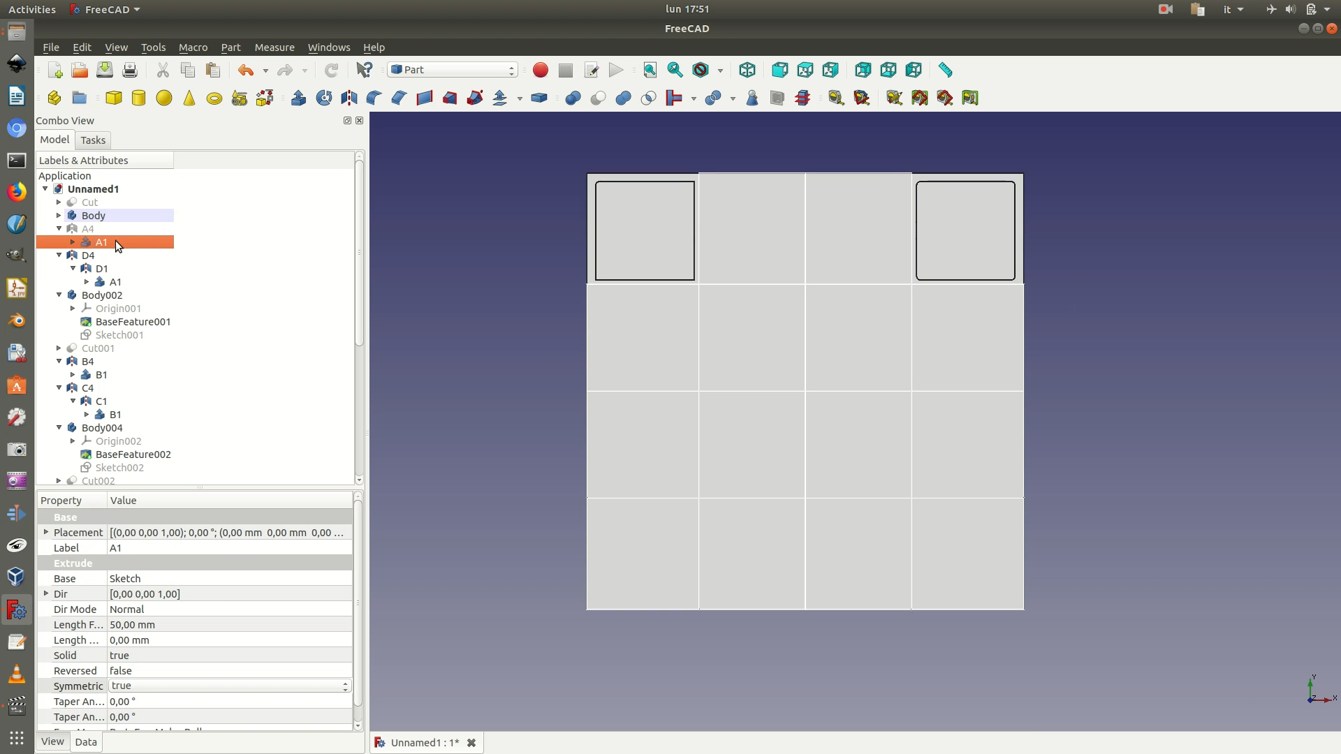
25. Hide all the elements from the left sidebar, except the first Cut element (the data layer with the grid cuts) and the A1 extruded block. Select the two of them and go through Part > Boolean > Intersection. The result will be a 12.75 x 12.75 block containing the first section of the data layer.
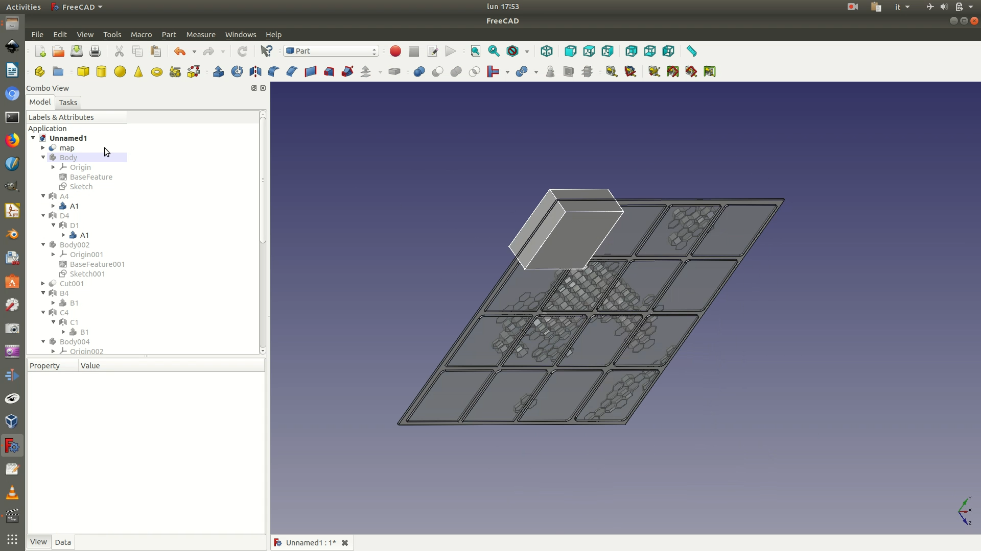
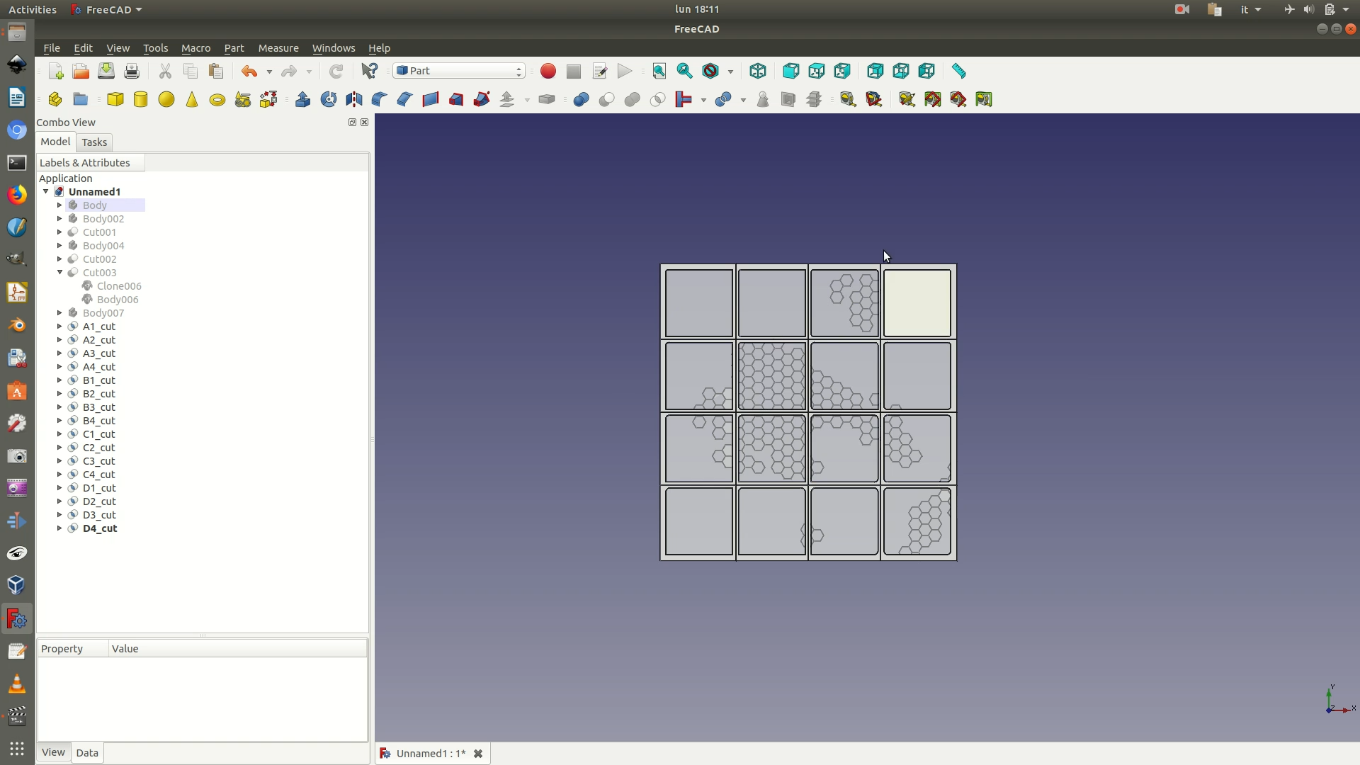
26. Repeat step 25 for all the 15 other blocks. The result is shown in the following image. Notice the names of the elements in the left sidebar, which follow the logic of A1_cut, A2_cut, etc.
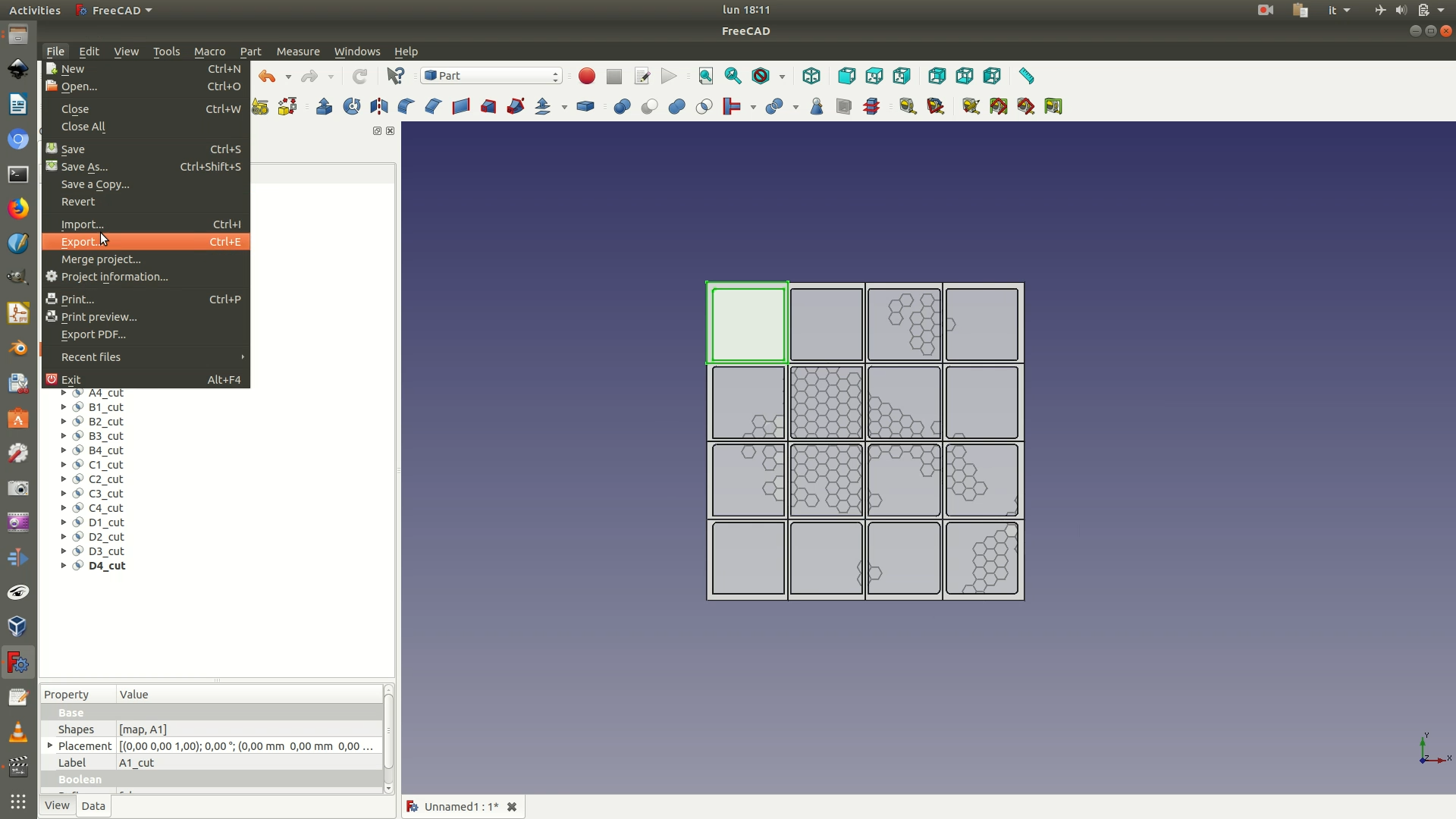
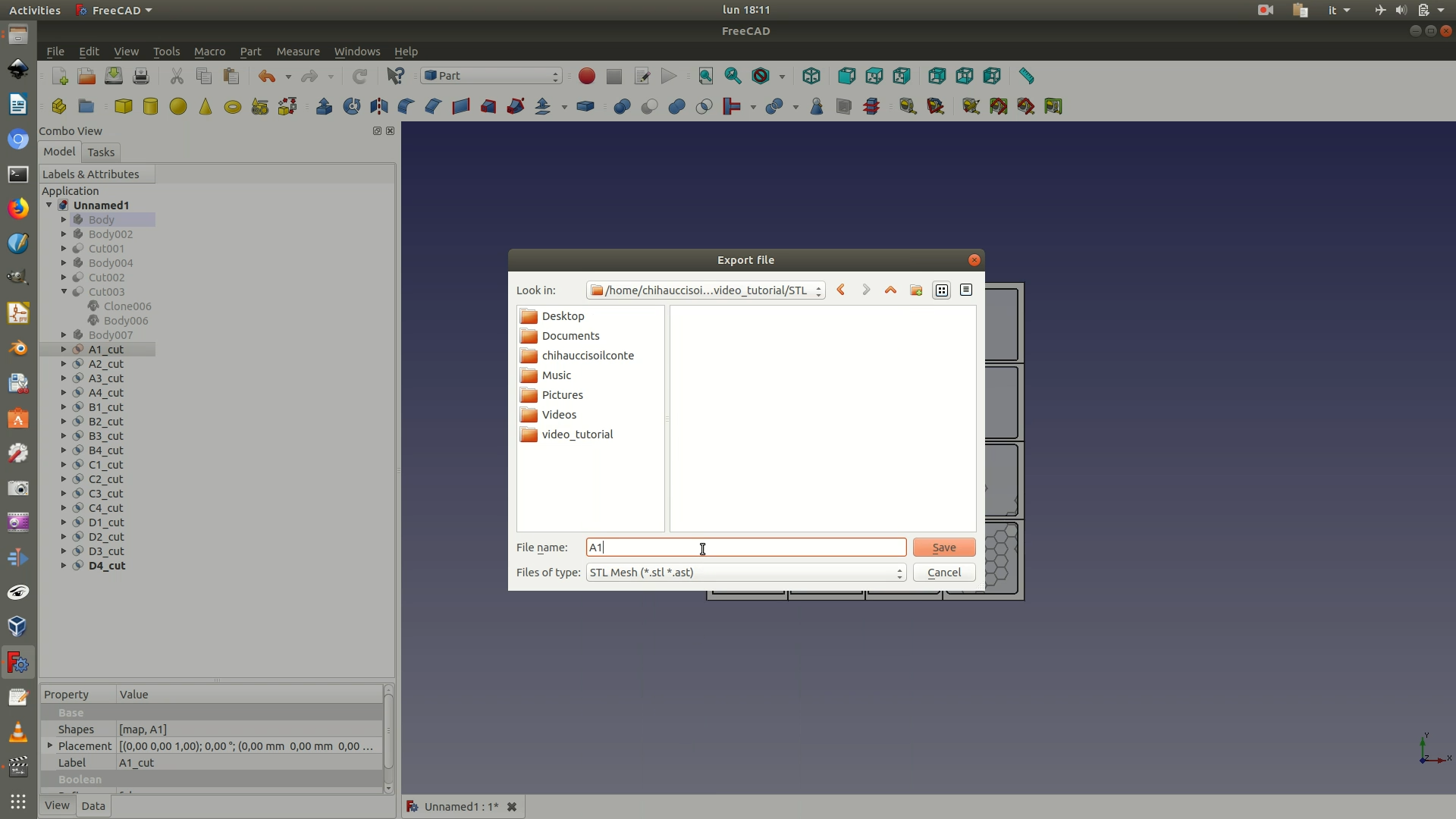
27. Select each of the Cut elements and export them one by one as STL files by going through File > Export. When choosing a filename, it’s easier if you stick to the A1, A2, etc. naming convention. Additionally, save the whole project as a FreeCAD file (.fcstd).
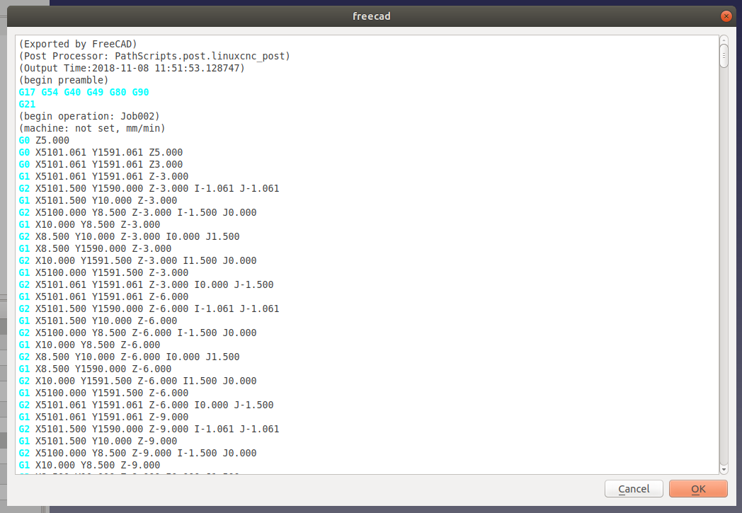
28. Open Slic3r. Slic3r is a software that processes a 3D model and generated instructions for the 3D printer, for example by slicing the volume into thin layers, creating supports for hanging elements, etc. The version of Slic3r used in this tutorial is a custom version tailored to the 3D printer used, a Prusa i3 mk3. The interface and the settings are however part of any Slic3r version you used. If you are using a general version of Slic3r, then you will need to set the configurations appropriately for your specific 3D printer. It’s wise to talk to the owner/operator of the 3D printer in this phase.
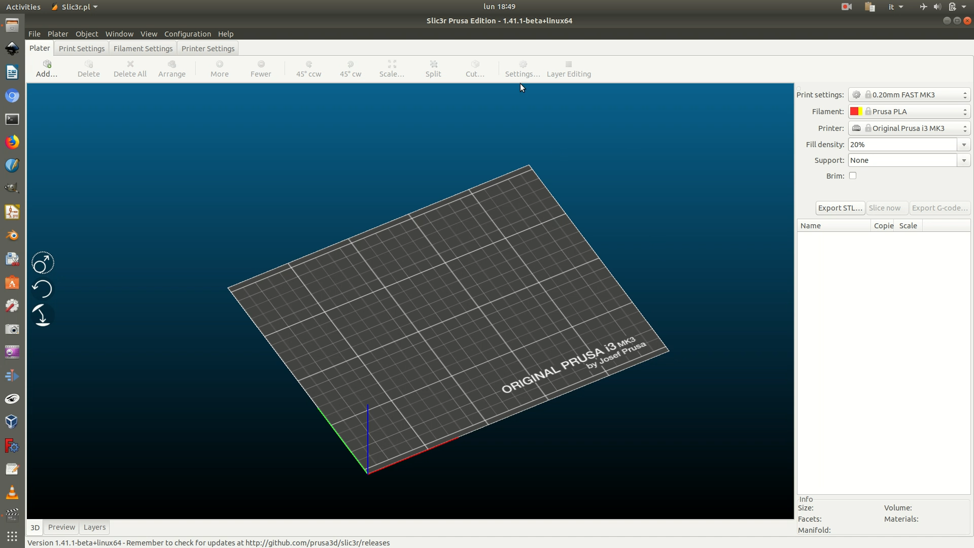
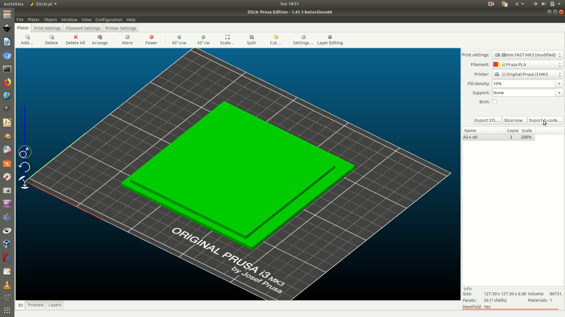
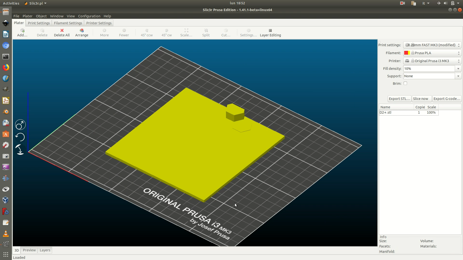
29. Click on the Add button from the top toolbar and import the .stl file for the first section of the data layer. The following steps will depend on whether the imported section is flat (representing a piece with no data, see second image) or presents one or more 3D hexagons (see third image).
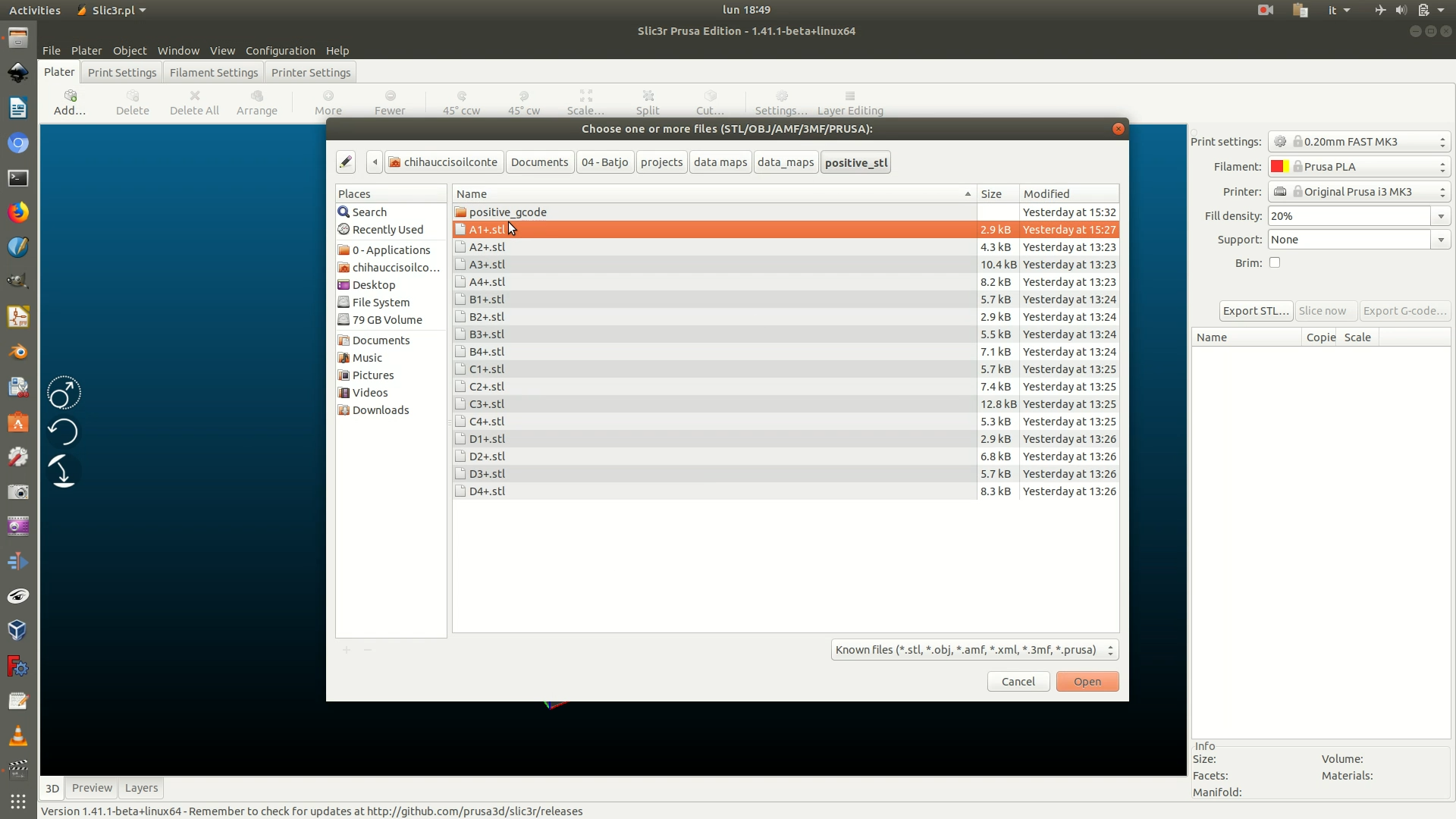
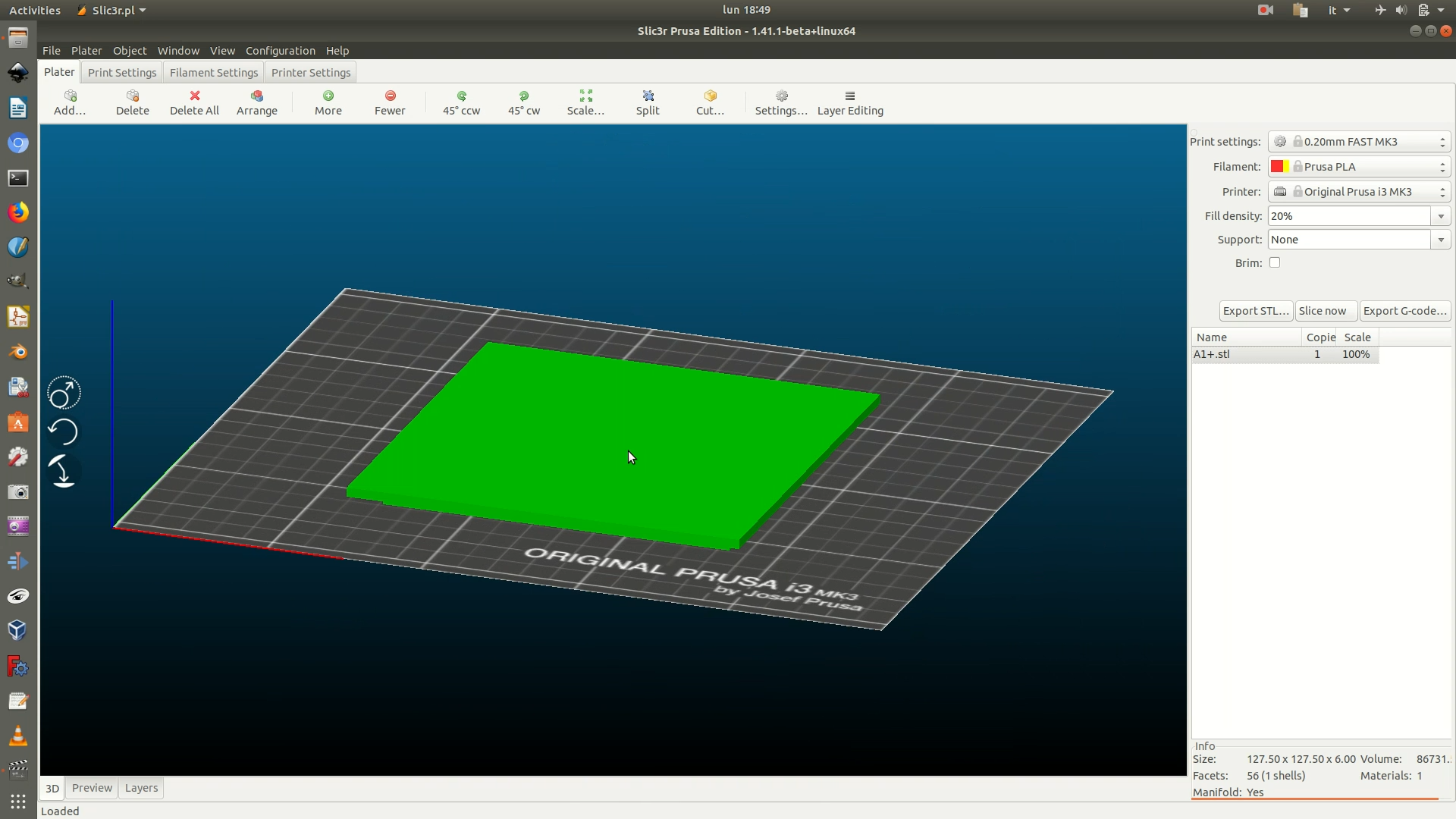
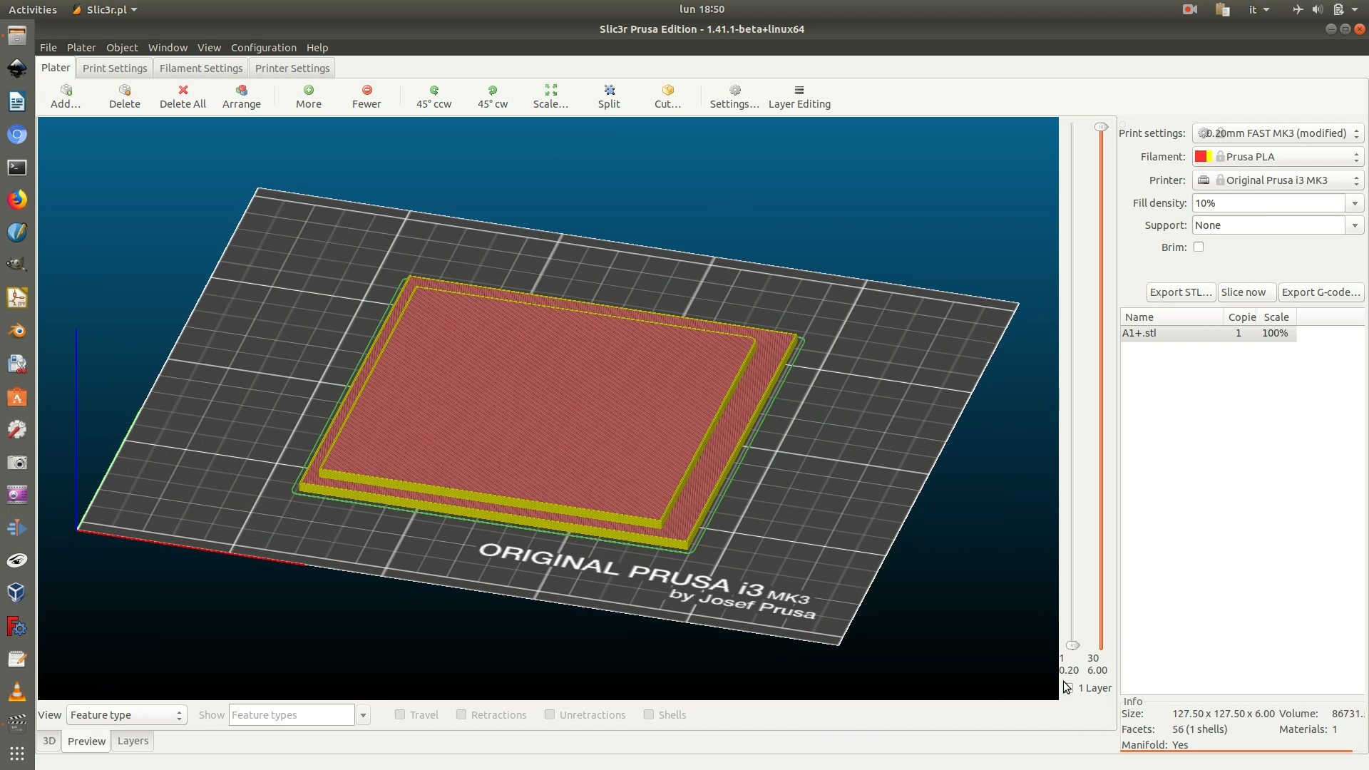
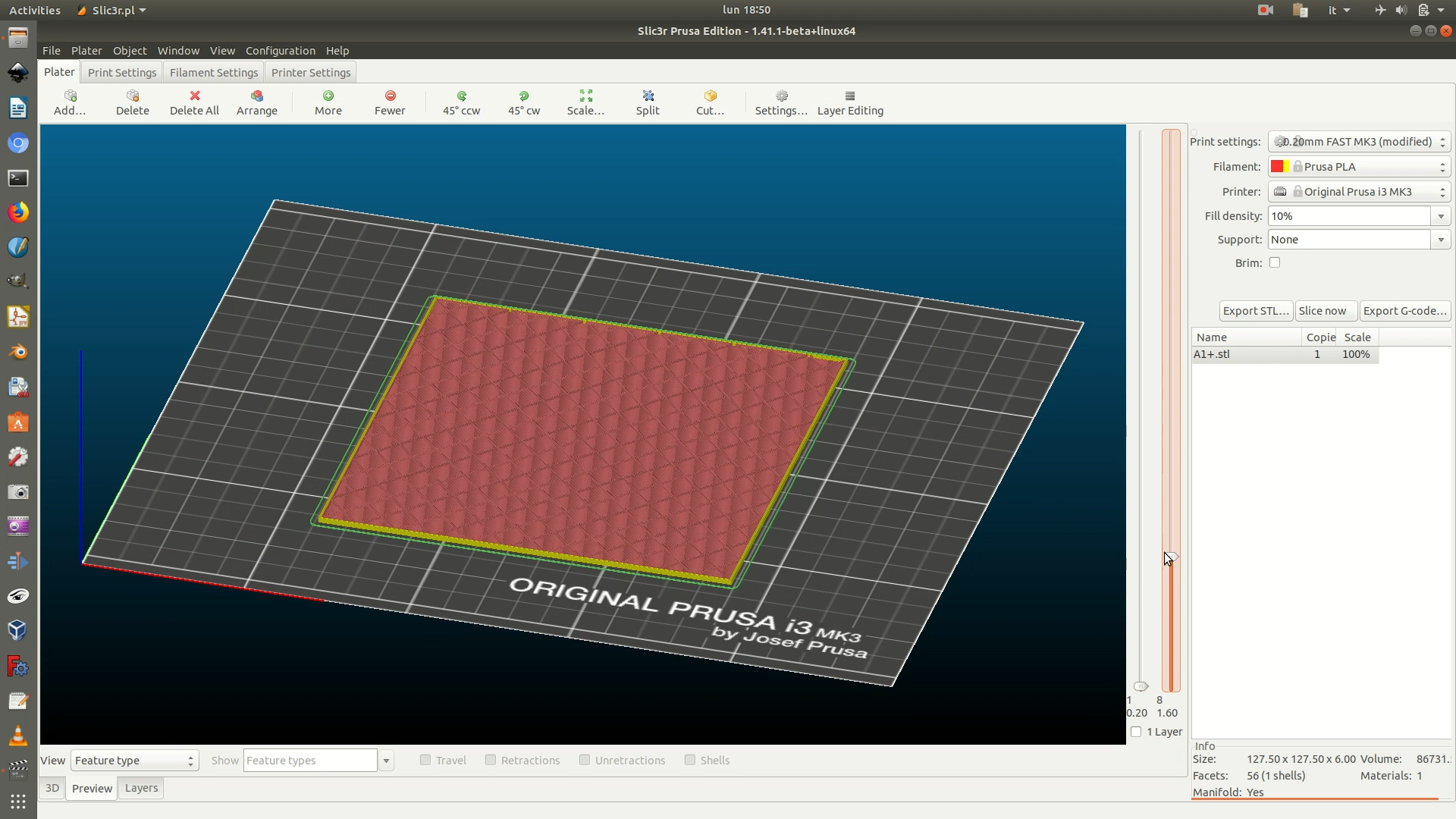
30a. Flat object with no 3D data hexagons. The base of the object is narrower than its top. For this reason, for optimal printing, you need to flip it, so that the wider part (the top) will sit on the printer’s bed. To do so, click on the object (it will turn green) and navigate through Object > Rotate > Around Y axis. In the dialog box that appears, type in a rotation angle of 180°.
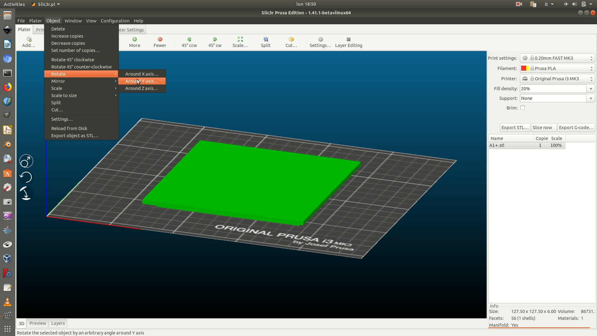
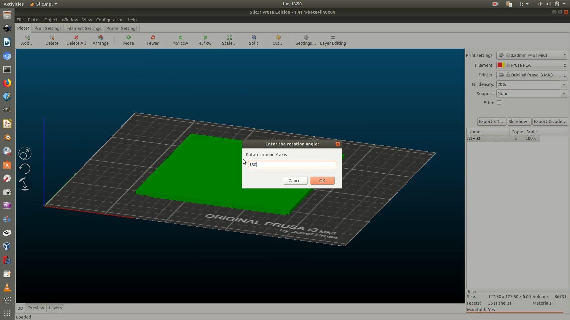
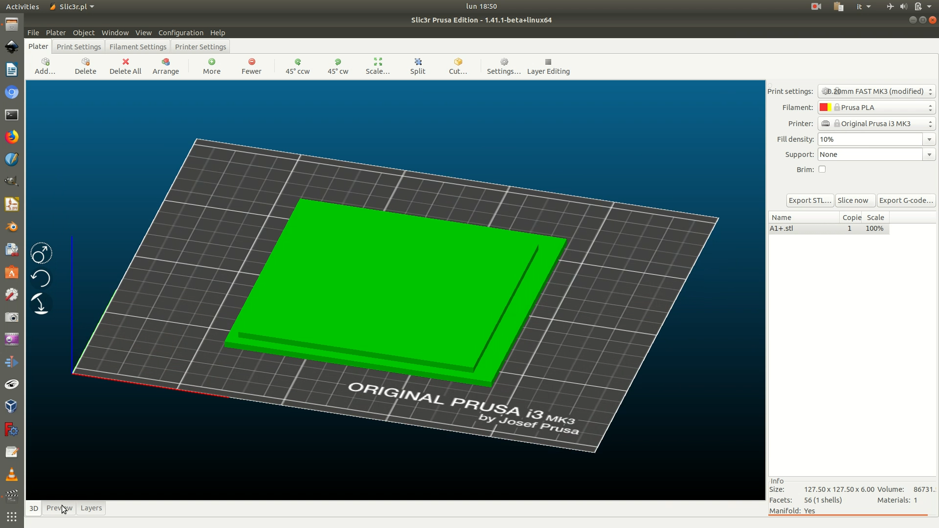
30b. Object with 3D data hexagons. You don’t need to flip the object and can proceed with the next step.
31a. Flat object with no 3D data hexagons. In the dropdown menus on the right, change the values to match the following options:
Print settings > 0.20mm FAST. This setting defines the height of each of the layers the objects gets sliced into for 3D printing.Filament > PLA. This setting defines the type of filament you will use to 3D print, and thus the temperature that the extruder has to reach in order to melt it and lay it.Printer >make sure the setup matches the printer you will use.Fill density > 10%. This value means that the only 10% of the piece will be filled, resulting in a light object with minimal material use. Because this is a decorative element that won’t need to endure particular pressure, a 10% fill density is certainly enough.Supports > none. This because the object doesn’t require any printing supports for hanging parts.
When you have defined all these parameters, click on Slice now.
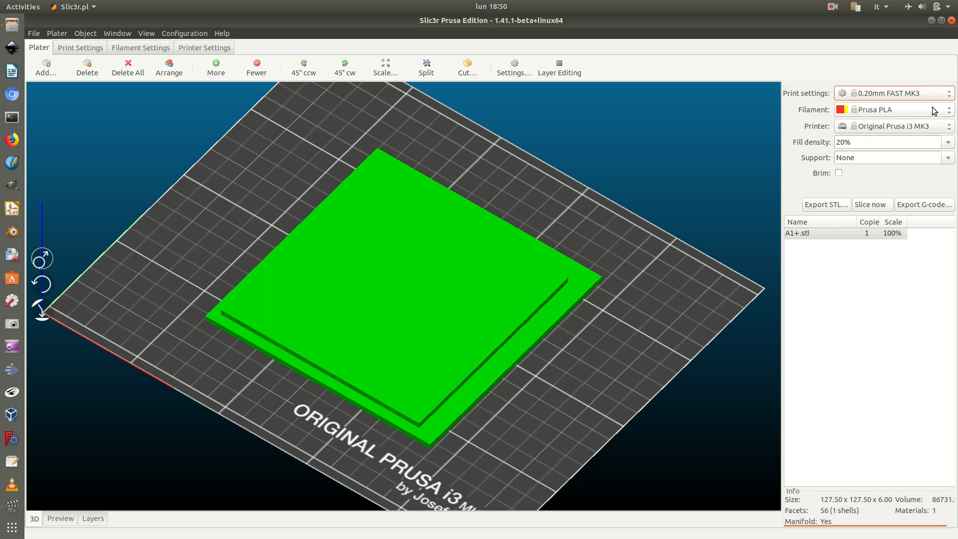
31b. Object with 3D data hexagons. In the dropdown menus on the right, change the values to match the following options:
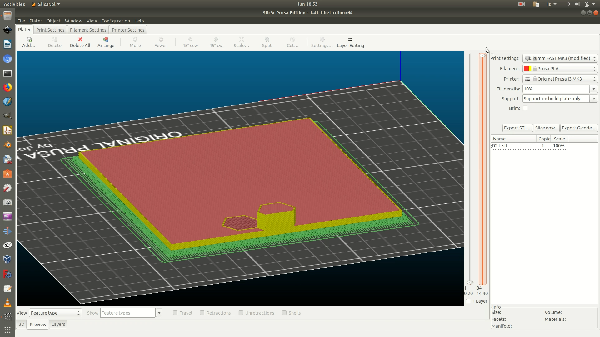
Print settings > 0.20mm FAST. This setting defines the height of each of the layers the objects gets sliced into for 3D printing.Filament > PLA. This setting defines the type of filament you will use to 3D print, and thus the temperature that the extruder has to reach in order to melt it and lay it.Printer >make sure the setup matches the printer you will use.Fill density > 10%. This value means that the only 10% of the piece will be filled, resulting in a light object with minimal material use. Because this is a decorative element that won’t need to endure particular pressure, a 10% fill density is certainly enough.Supports > Support on build plate only. This because the base of the object is narrower than the top, but we can’t flip it since there are 3D hexagons on the top. Setting this parameter will create supports for the hanging part of the base.
When you have defined all these parameters, click on Slice now.
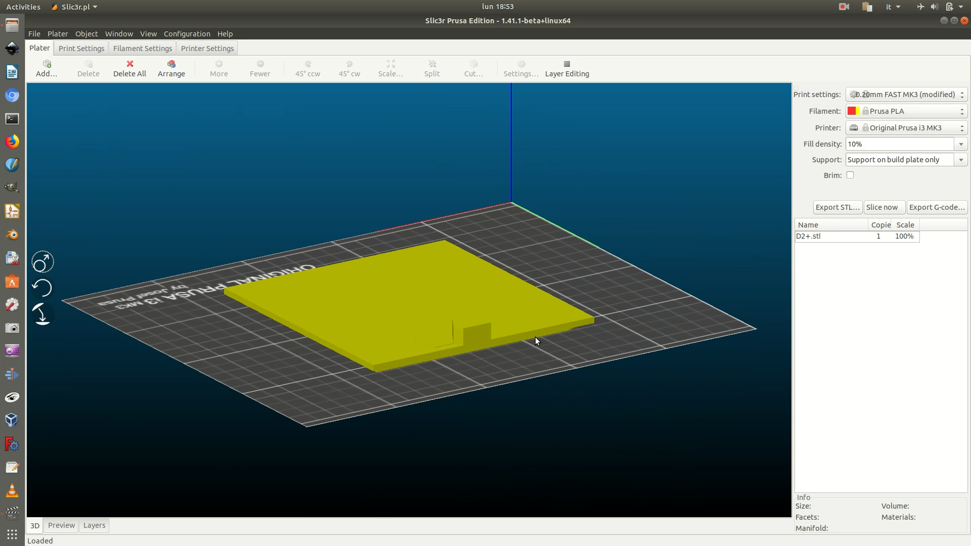
32a. Flat object with no 3D data hexagons. Click on the Preview tab, from the lower left side of the window. This will show you a preview of the movements the machine will make. You can play with the sliders on the right to check if the output is as desired.
32b. Object with 3D data hexagons. Click on the Preview tab, from the lower left side of the window. This will show you a preview of the movements the machine will make. You can play with the sliders on the right to check if the output is as desired. As you can see there are some green lines: they represent the supports you created in the previous step.
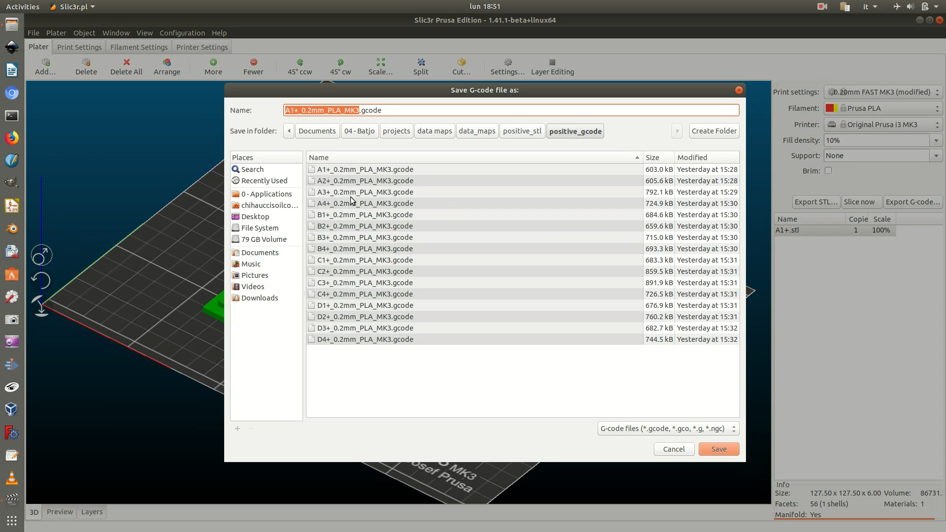
33. Click on the Export G-code button on the right and save the file.
