3D Modeling · 3D Data Map
Part 3 - The two 3D data layers
Full Video Tutorial
Workflow explanations
Download final 3D modeling files
0. As a prerequisite, you need to have installed the BlenderGIS Addon, which will allow you to open geo data in Blender.

1. Open the software Blender. Note that you need a mouse in order to use Blender. Additionally, because the interface could be rather confusing to novice users, we’ll use keyboard shortcuts rather than guiding you through the exact location of buttons and commands. In you are interested in the actual buttons and menus clicked, have a look at the full video. The default layout presents a cube, a light source (represented by the black dot) and a camera (represented by the transparent cone). As a first thing, you need to delete these three things by selecting them and hitting the delete key. Note that, in Blender, you select objects by right-clicking on them (not the usual left-click). You will end up with only the XY plane in the layout window.

2. Import the .STL map you had previously modeled in FreeCAD. It will serve as guidance as to where to position the data layers. To do so, click through File > Import > Stl and select the appropriate file.


3. Import the first .SHP file map layer, the one with the hexagon grid map filtered for the negative values. Do so by going through the menu File > Import > Shapefile. (You won’t see this option if you don’t have the BlenderGIS addon installed). In the pop-up window that appears, fill in the following options and click OK.
Extrusion from field: tick the checkboxField: choose the filed name of the variable containing the absolute value of the attribute you want to use for elevationExtrude along: Z axisSeparate objects: tick the checkboxCRS: select the appropriate CRS (matching the CRS in which you exported the layer)
By default, all the hexagonal polygons you have just imported will be select. Do not deselect them.


4. After the import, the camera will be very zoom out, in order to include the new file in view, and you might not see the .stl map you imported in step 4. Don’t worry, it’s still there and in this step you will scale the hexagonal polygon layer to the same size as the .stl map. Start by choosing a top view, by clicking on the key 7 on the keyboard. Then press the Z key to switch to Wireframe mode. In this visualization mode, the polygons become transparent and so you can see the map below to match their position.
Press the S key on your keyboard, which activates the scale command. Move your mouse cursor until you achieve the desired size, so that the polygons match the shape of the map below. In the course of the scaling process, you might need to stop and readjust the position of the hexagonal grid. You can do so by pressing the G key and moving the cursor to move the object and then pressing the S key again to scale it further.
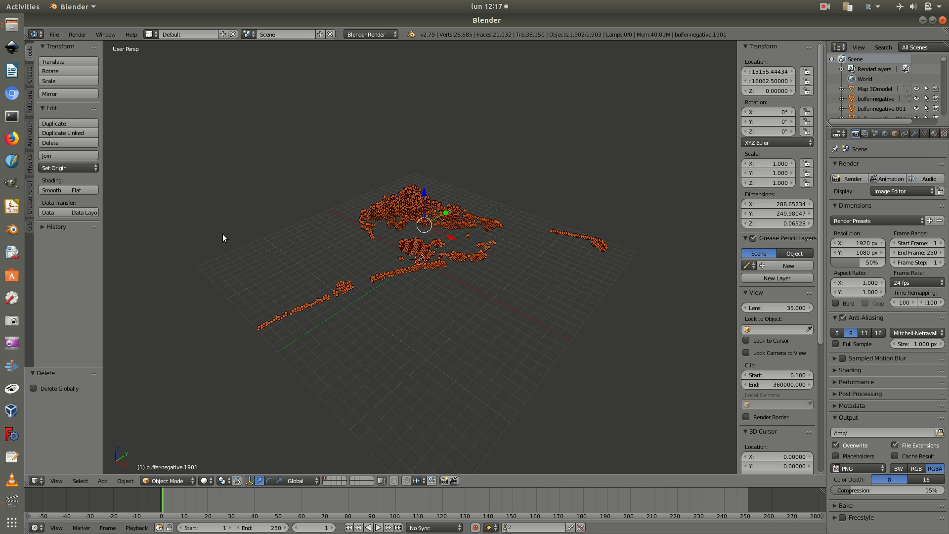
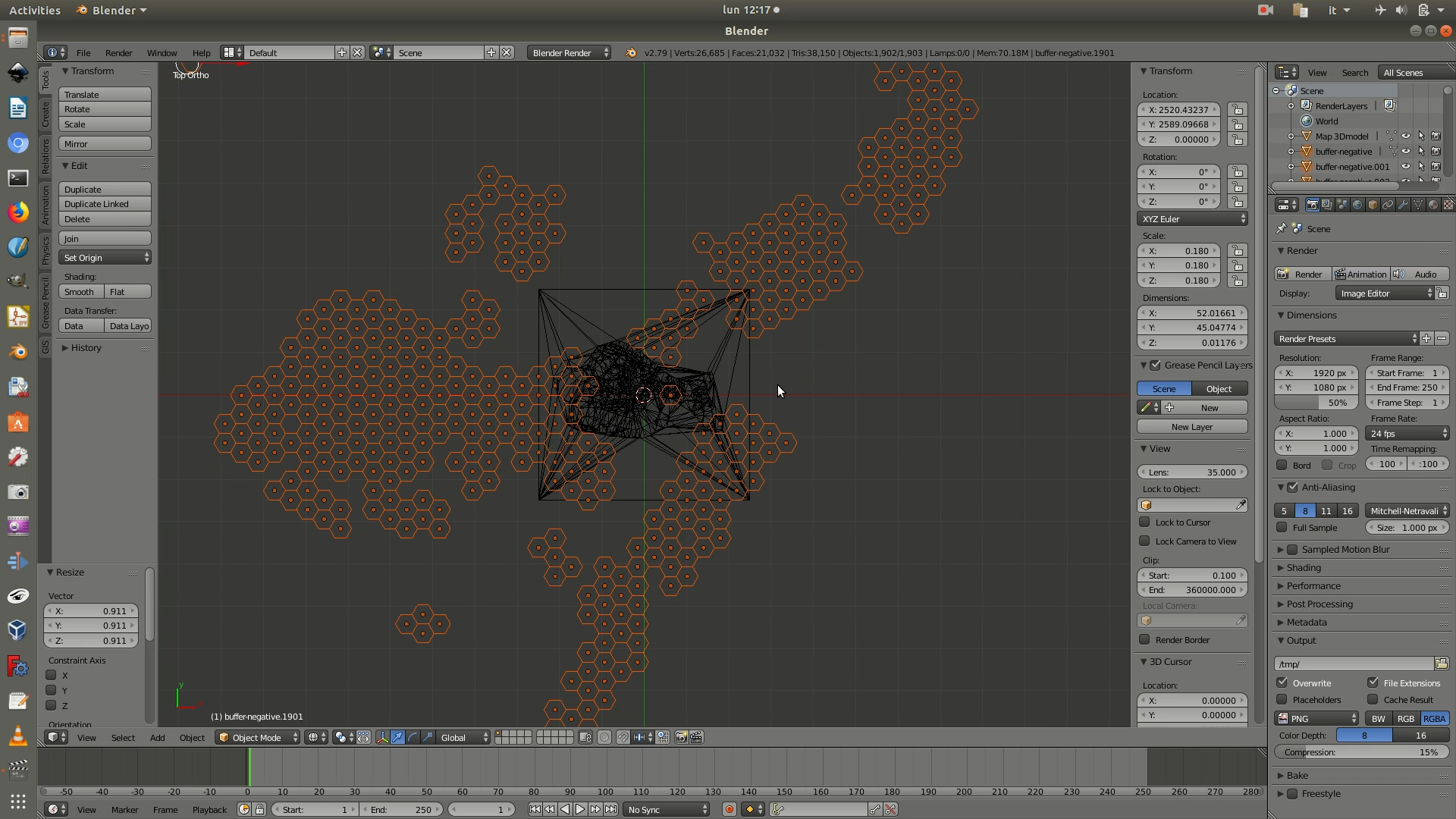
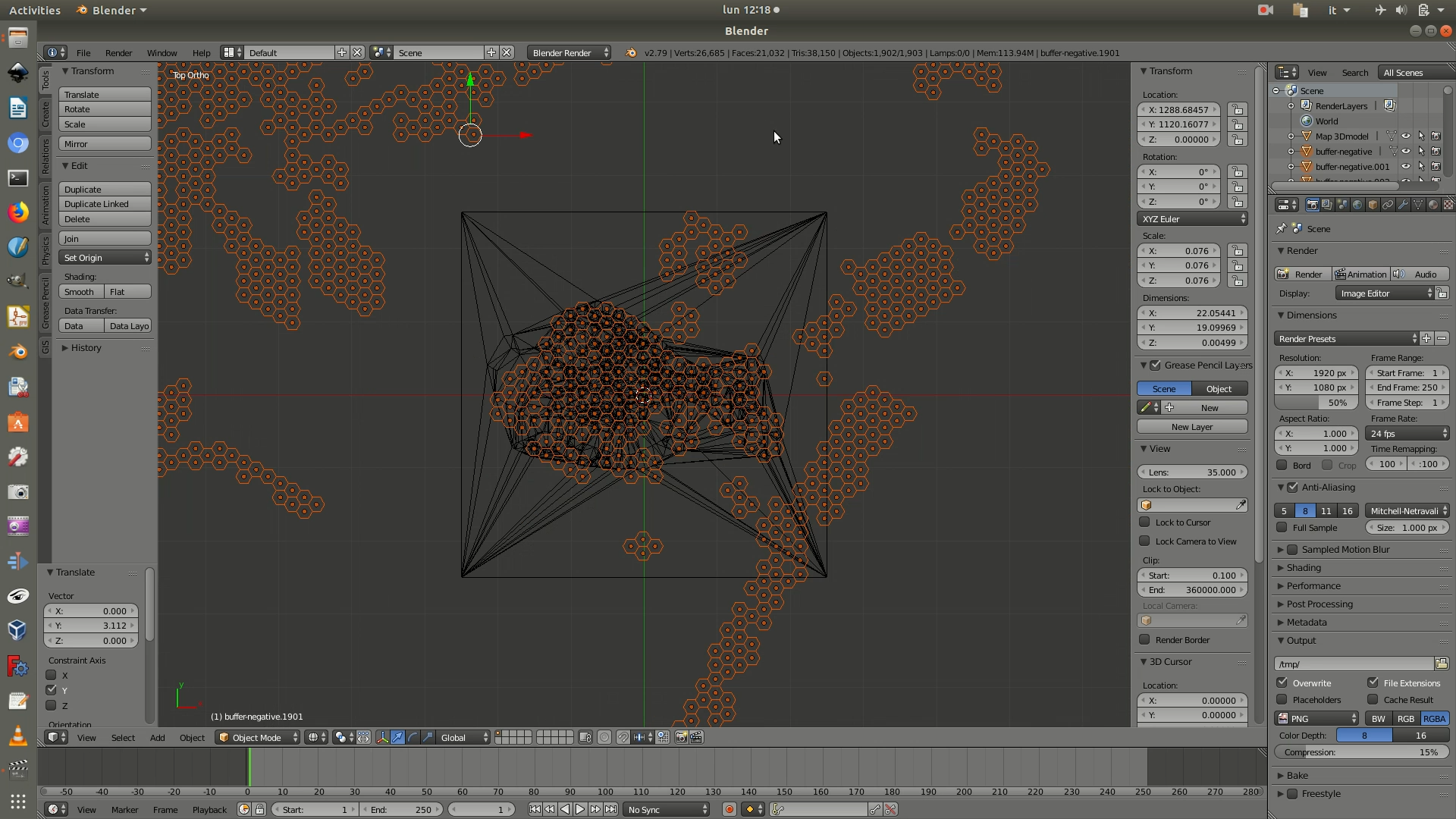
5. Press the A key to deselect your hexagonal polygons. Delete any of the hexagonal polygons that are outside of the square map area, as they are not part of the map you will send in production. You can delete them faster by activating a box selection by pressing B on your keyboard. The selection might take a bit to process depending on its size. When the polygons are selected they’ll turn orange and you can press the delete key to remove them.
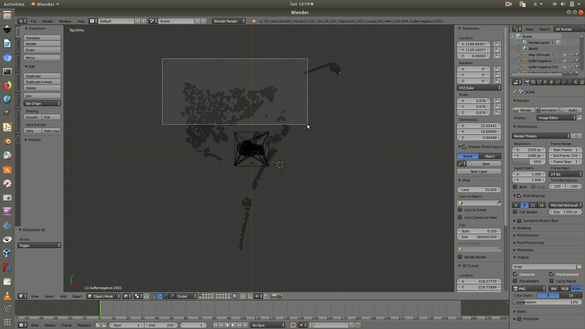
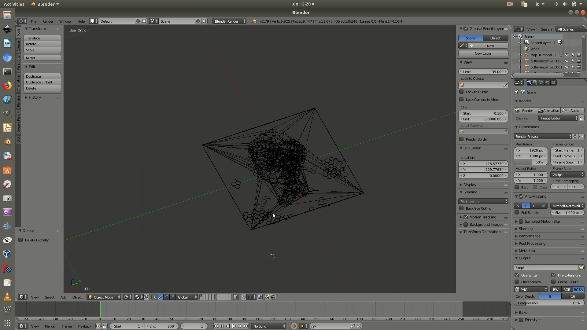
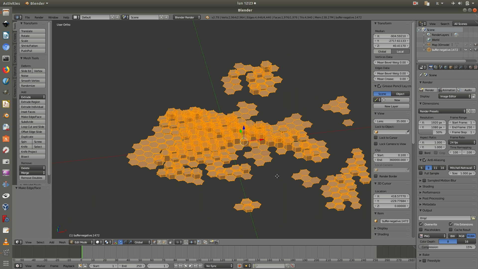
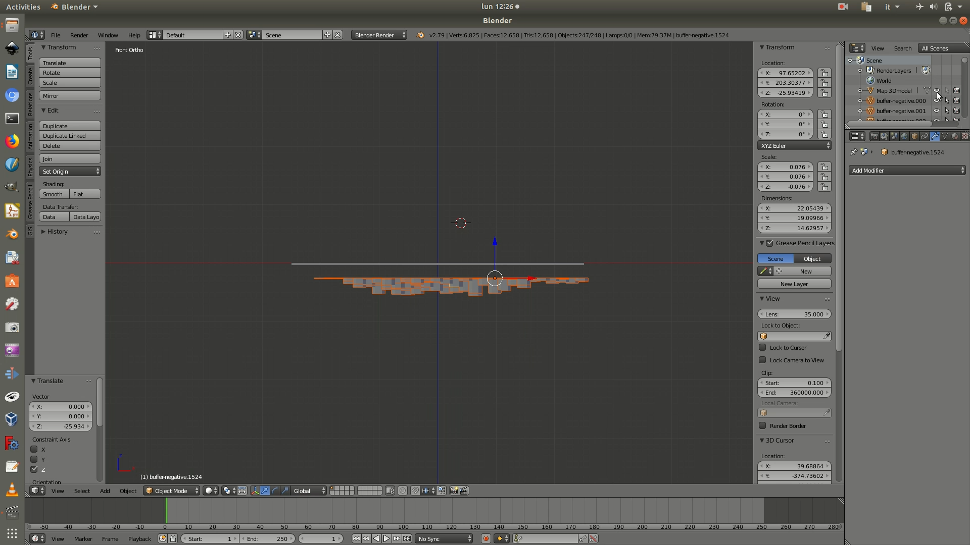
6. Select the .stl base map and make it hidden and not selectable by clicking on the eye icon and on the cursor icon shown in the first image below. Press Z again to switch from Wireframe mode to Solid mode and see what the 3D hexagon grid with negative values looks like. If you navigate to the bottom of the grid, you will see that these hexagons don’t have a base. You will need to fix these holes in the mesh because digital fabrication machines, unlike digital 3D visualizations, need complete solids to work with.
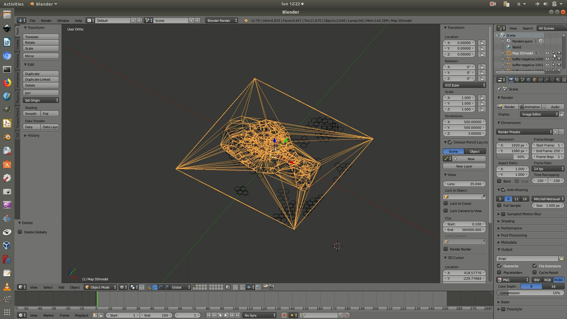
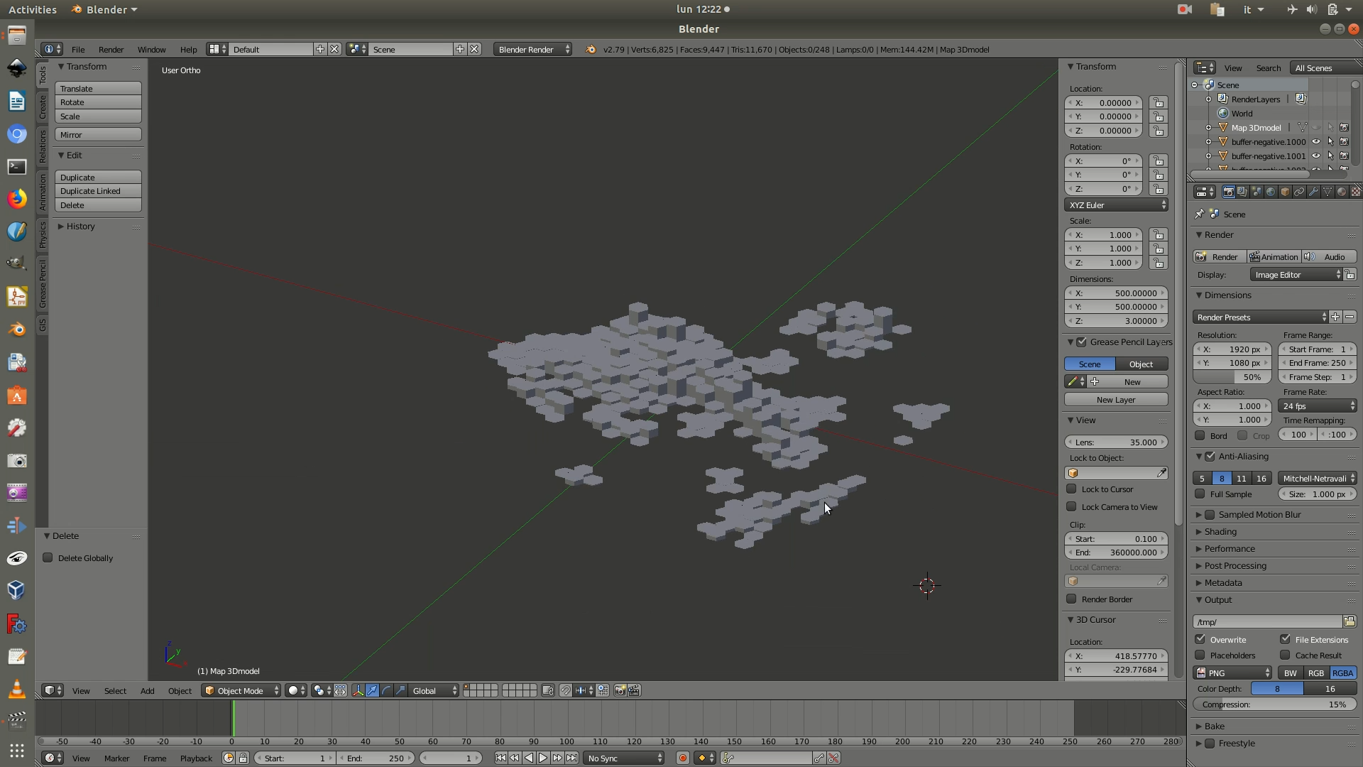
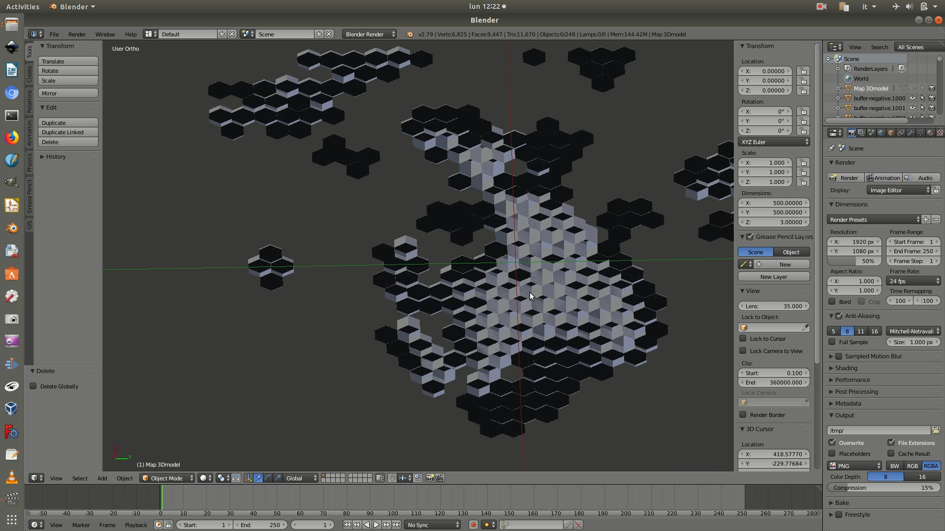
7. Select all the hexagonal polygons by pressing the A key. Hit the spacebar and a search box will appear. Search for join and click on Object:Join among the search results. This will transform all the single hexagonal polygons into a single object. Press the Tab key, to switch into Edit mode. You will know that you are in Edit mode because the edges of your objects will have turned black. Edit mode allows you to interact and modify the structure of the mesh.
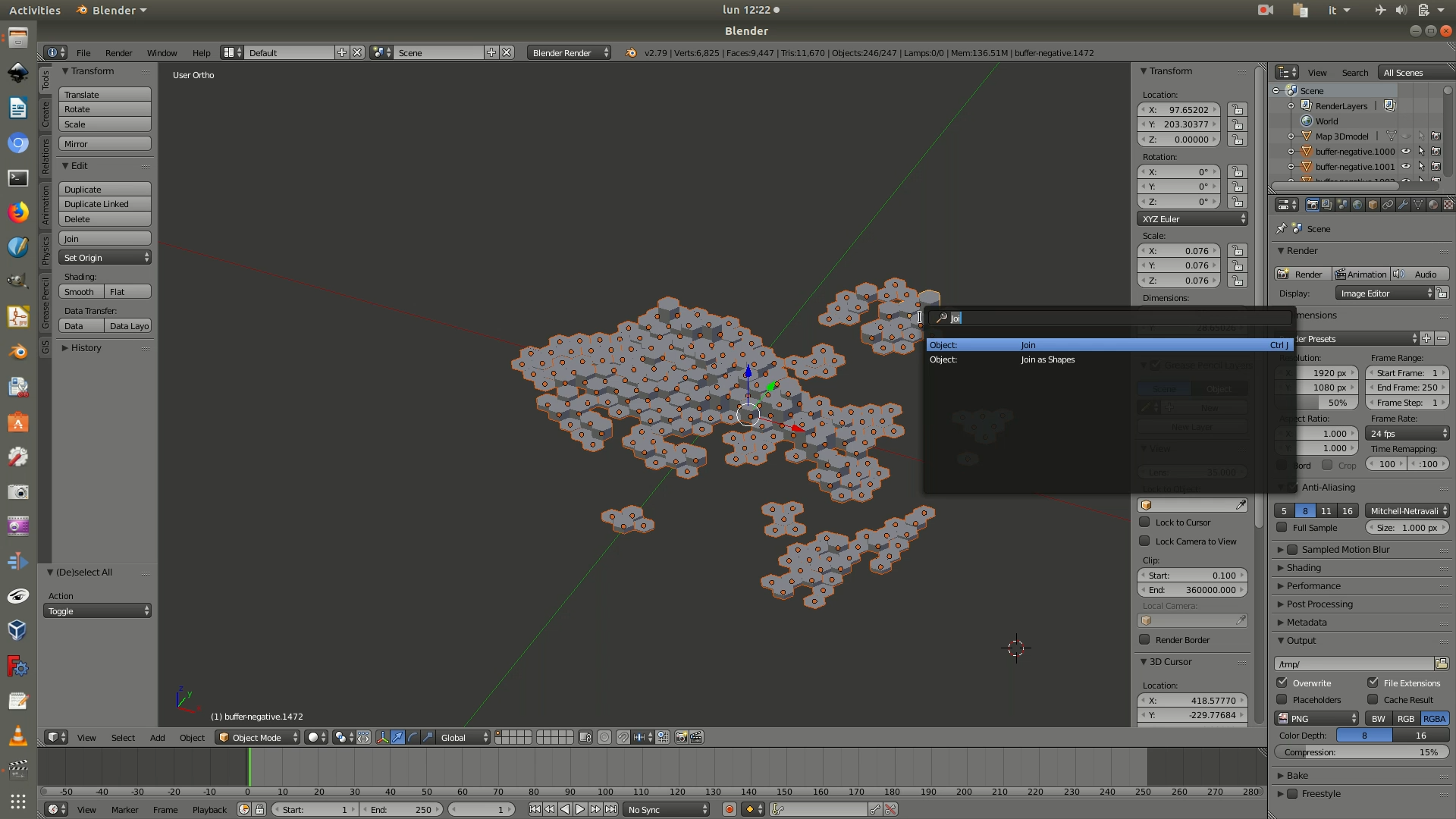
8. Select all the hexagonal polygons again by pressing the A key. Then press the F key to activate the Face command, which automatically generates a face to fill all the vertices that are not yet connected. In practice, this will create a base to close all the 3D hexagonal polygons and transform them into complete hollow solids.
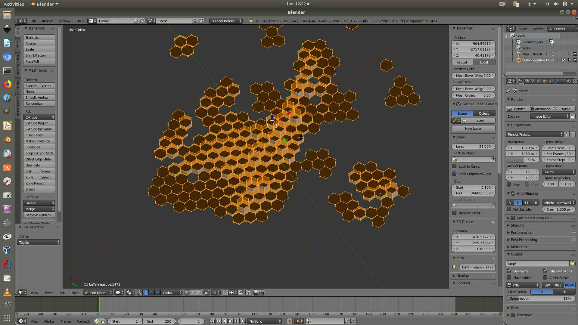
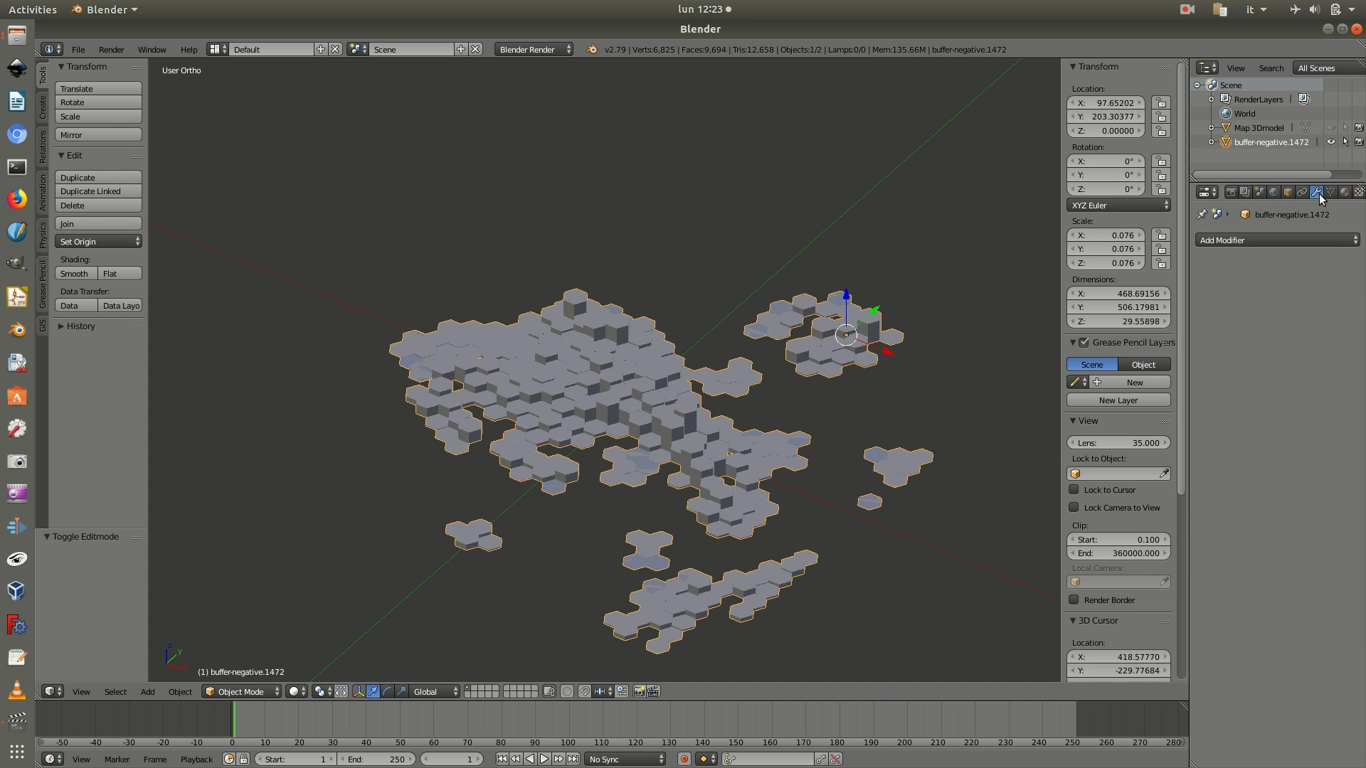
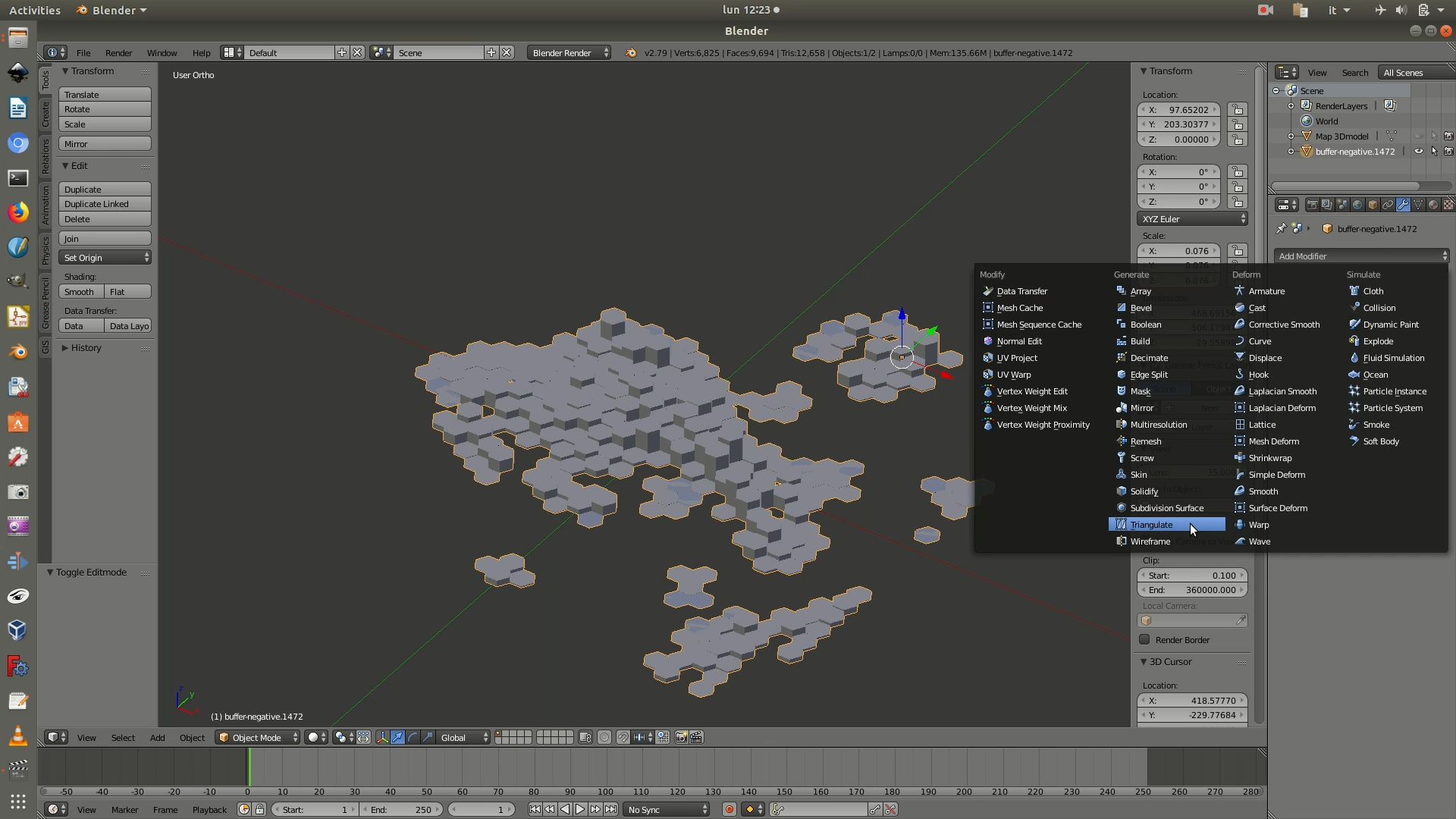
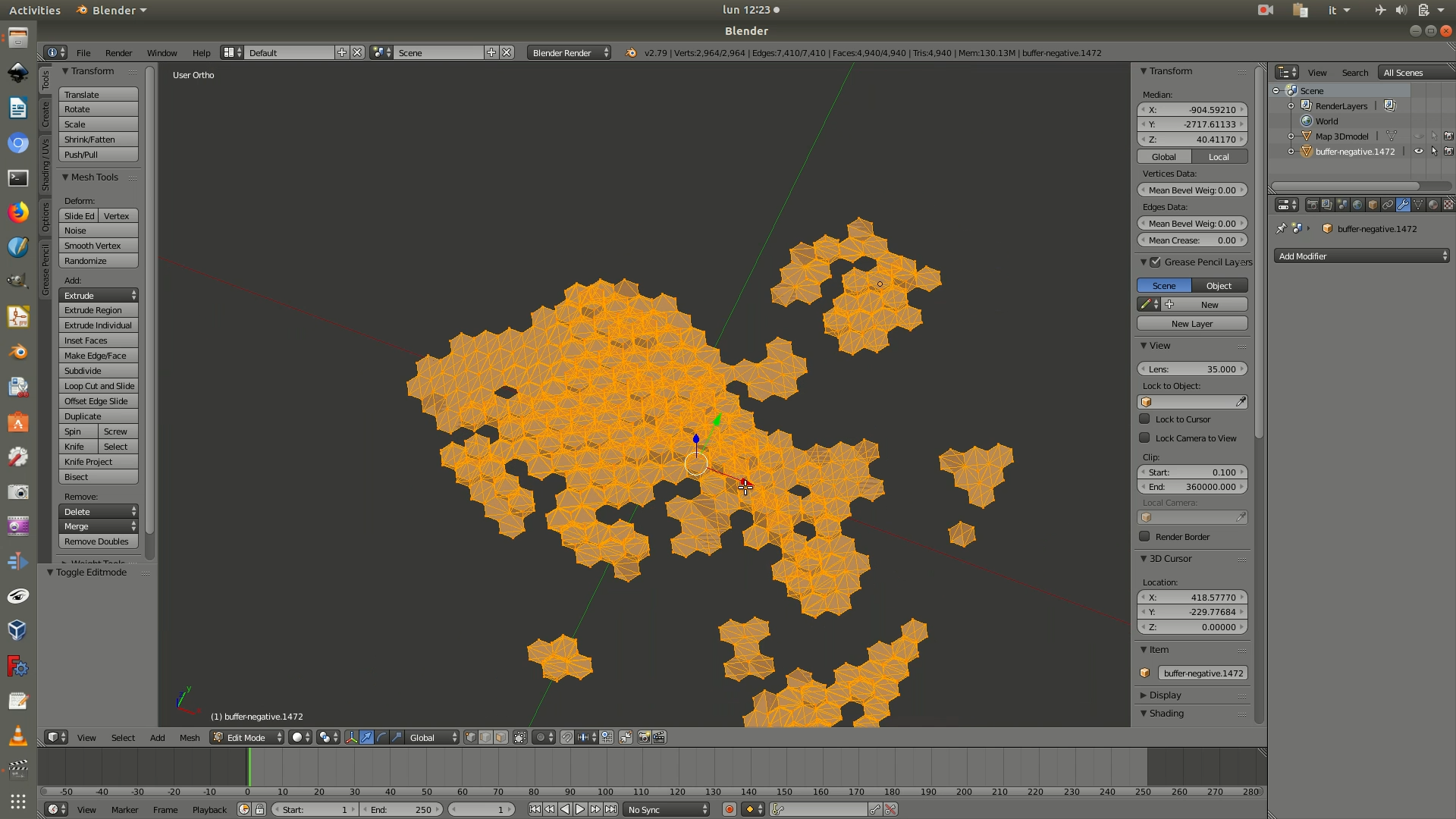
9. Press the Tab key again to exit the Edit mode and switch to Object mode. On the right-hand panel you will find the icon to access the Modifiers menu, which resembles a wrench (see image below). Click on it and go to the Add Modifier dropdown menu. Select the Triangulate modifier and then click the Apply button. Modifiers are algorithms/commands that modify the mesh. The Triangulate modifier splits the polygons of the selected mesh into triangles. In short, this command allows you to generate a more complex, detail-dense mesh, making it less likely to trigger glitches when imported in other software. You can check that the triangulation took place efficiently by clicking the Tab key and verifying that the mesh is now made up of triangles.
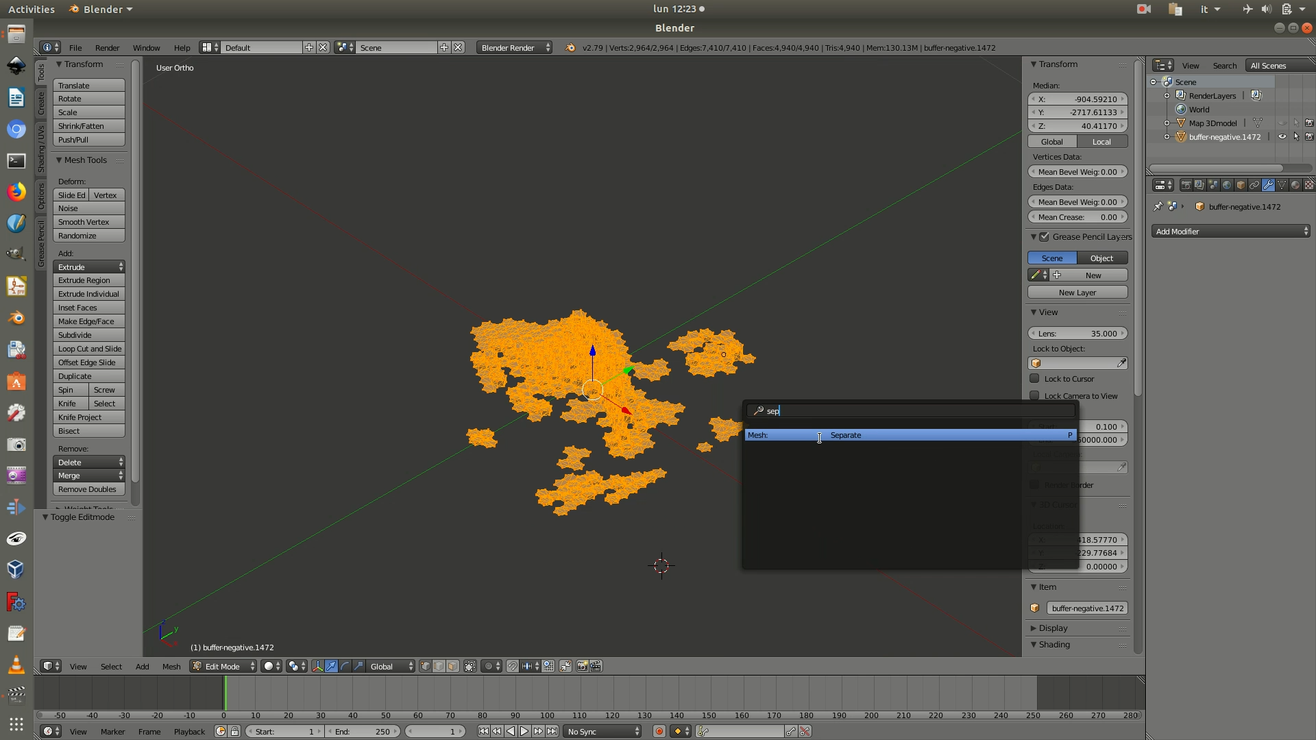
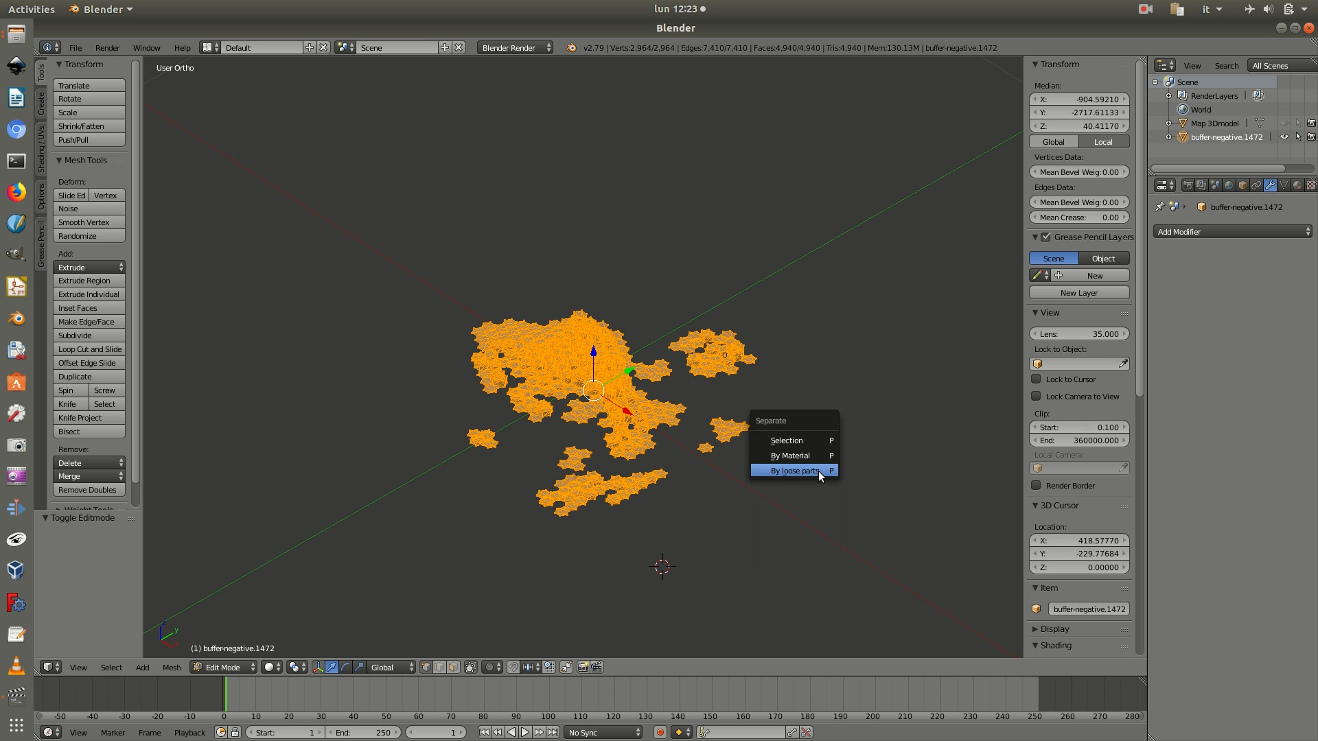
10. Hit the spacebar and a search box will appear. Search for separate and click on Mesh:Separate among the search results. On the pop-up that appears, select the By loose parts option. As a result, the hexagons will go back to being single objects, canceling the join you had applied in step 9. (The reason of the join was solely to apply the Face and Triangulate commands once, rather than for each hexagonal polygon).
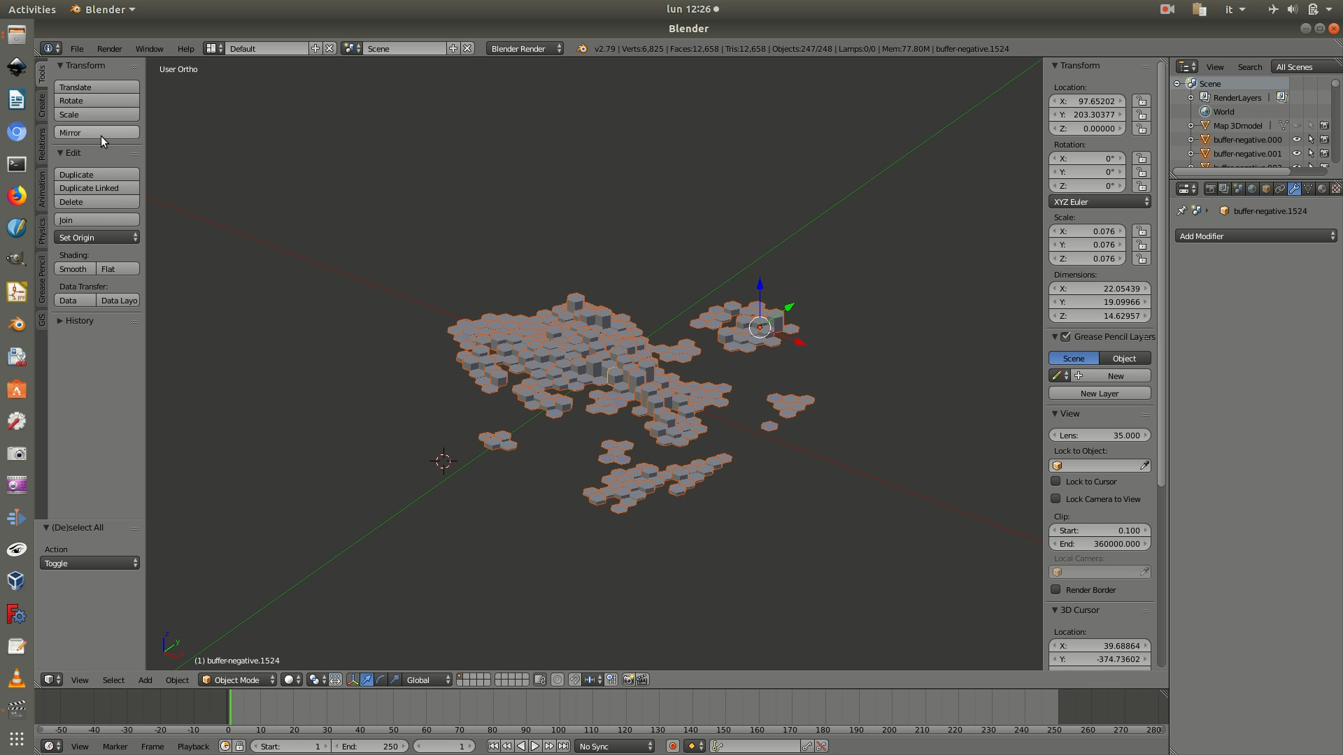
11. Press the A key to select all polygons again. On the Transform menu on the left side of the screen, click on the Mirror command. When the command becomes active, press the Z key to mirror it along the XY plane. The reason for this is that this layer represents the negative values, which will go below the map.
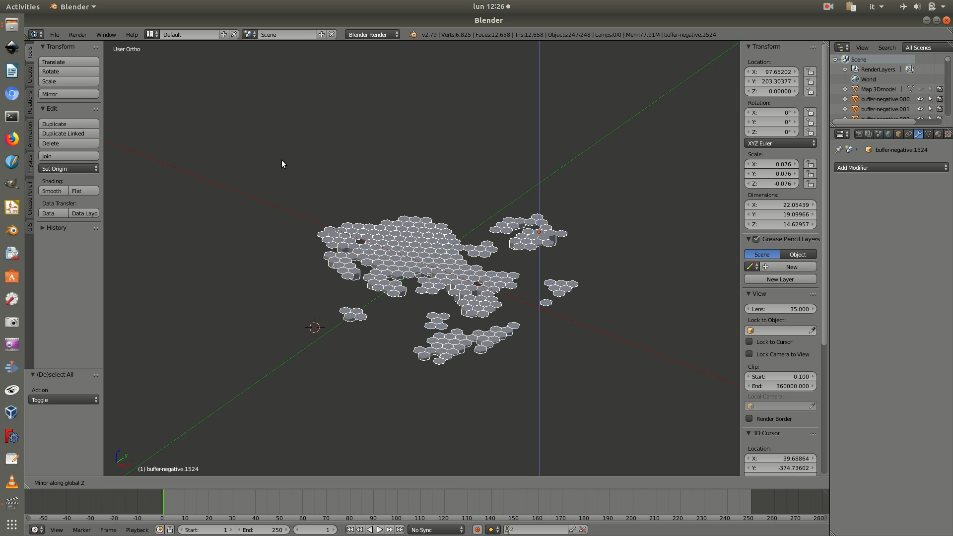
12. As a final check, unhide the base by clicking the hide icon shown in the image below. You can now double check that the data hexagons are correctly positioned in regard to the base map.
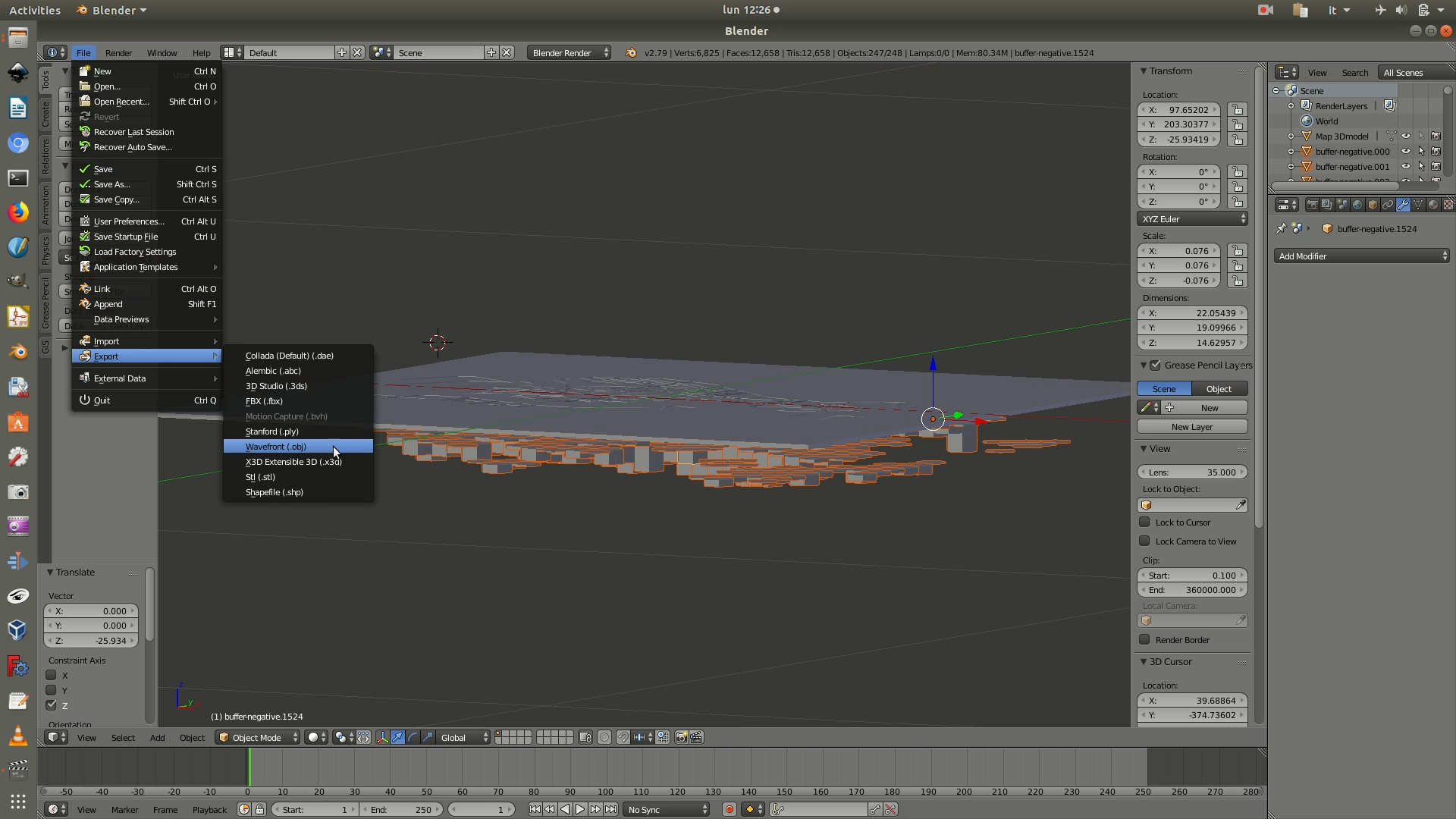
13. Select all the hexagons by pressing the A key. To save the file, go through File > Export > Wavefront (.obj). When the save as window opens up, there will be a few options on the left panel. Leave everything with the default values, except:
Up: chooseZ UpSelection only: checkbox checked
Refer to the image below to see what all the options should look like. Then click on Export obj from the top right corner.
Then, also save your file as a Blender project, with the .blend extension, by going through File > Save as.
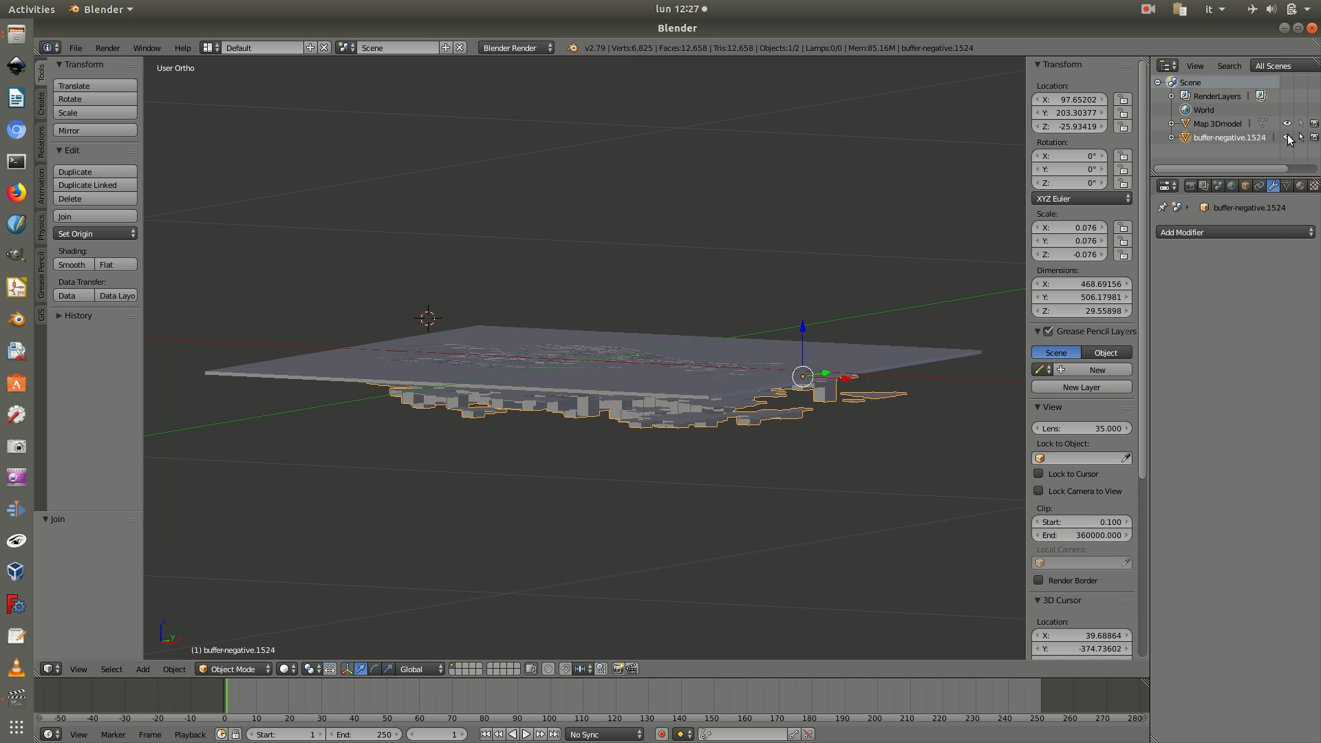
14. Hide the mesh with negative values hexagons by clicking on the eye icon and make it not selectable by clicking on the cursor icon shown in the image below. You are now ready to work with the positive values layer.
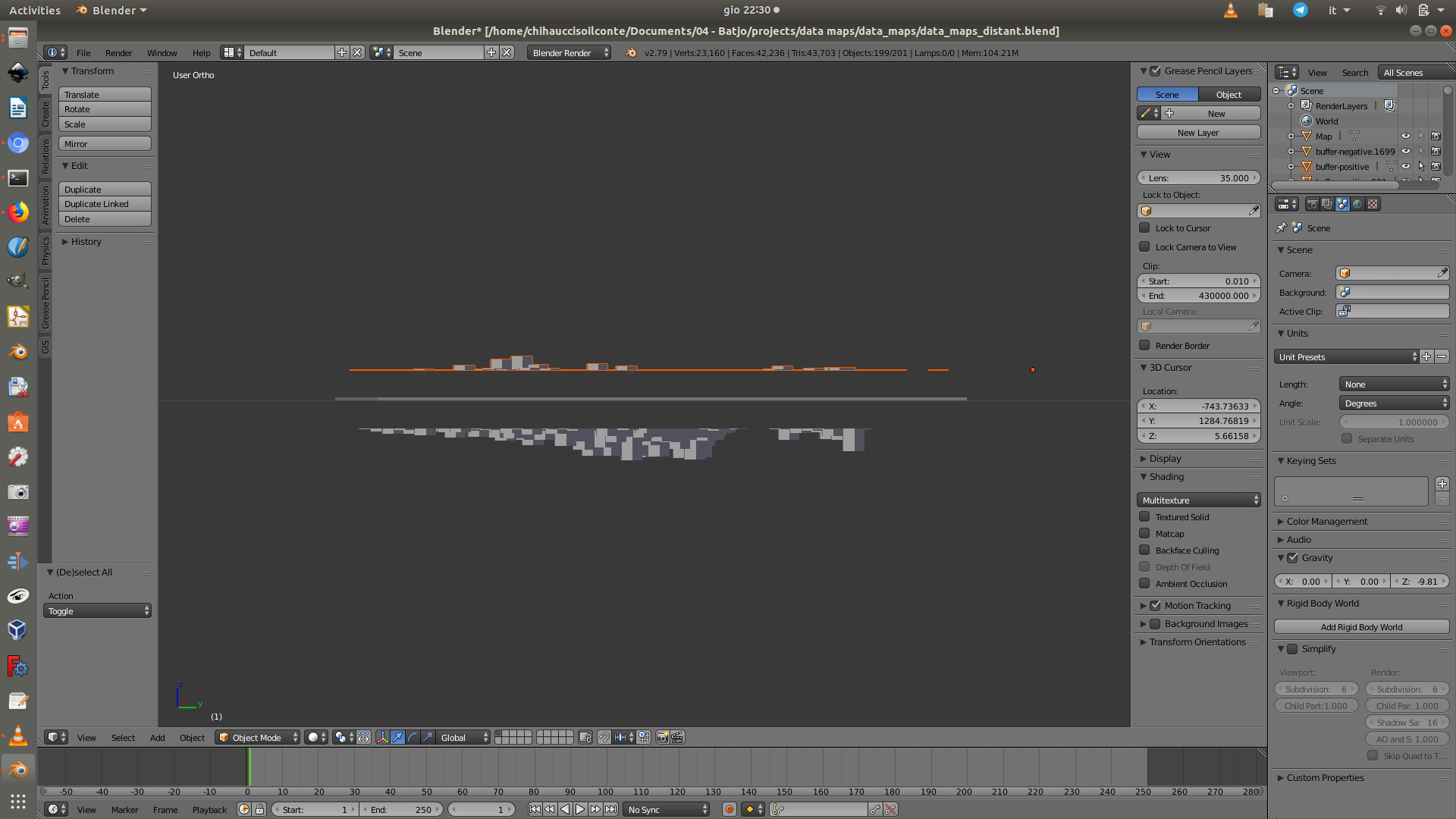
15. Repeat steps 3 to 12 of this tutorial section, only by uploading the .SHP file with the map layer filtered for positive values. Then, skip step 13 and proceed with step 14 and 15 to complete the 3D modeling of the positive and negative data layers.
16. Switch software and open FreeCAD. These last steps are needed to attach the hexagon polygons onto a thin support base, so that they can then be 3D printed. Create a new project by going through File > New. Then import the first file (the one with negative values) by going through File > Import. In the select module that appears, select Wavefront OBJ - Arch module (importOBJ).
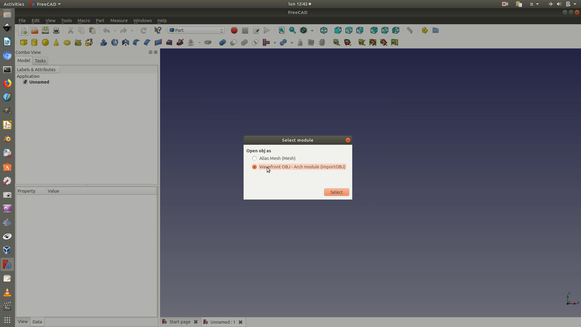
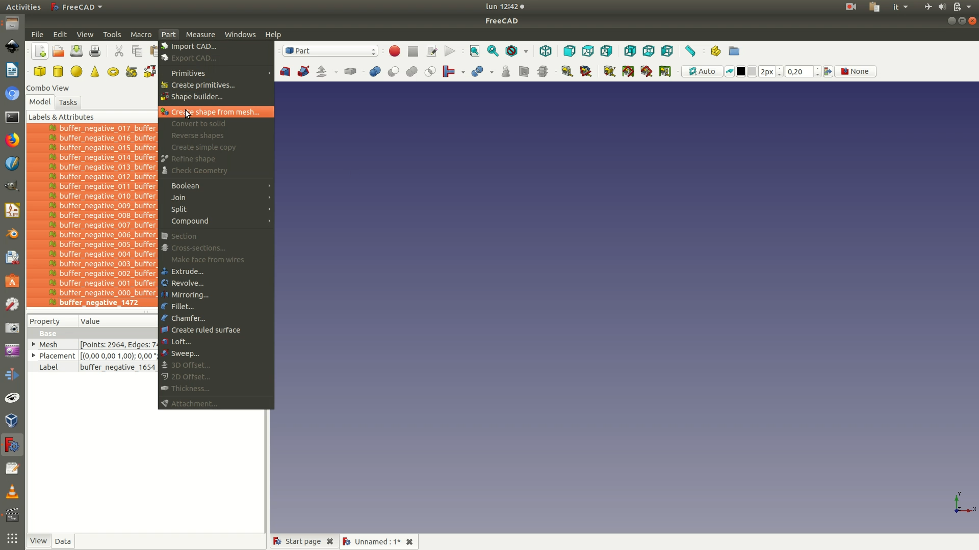
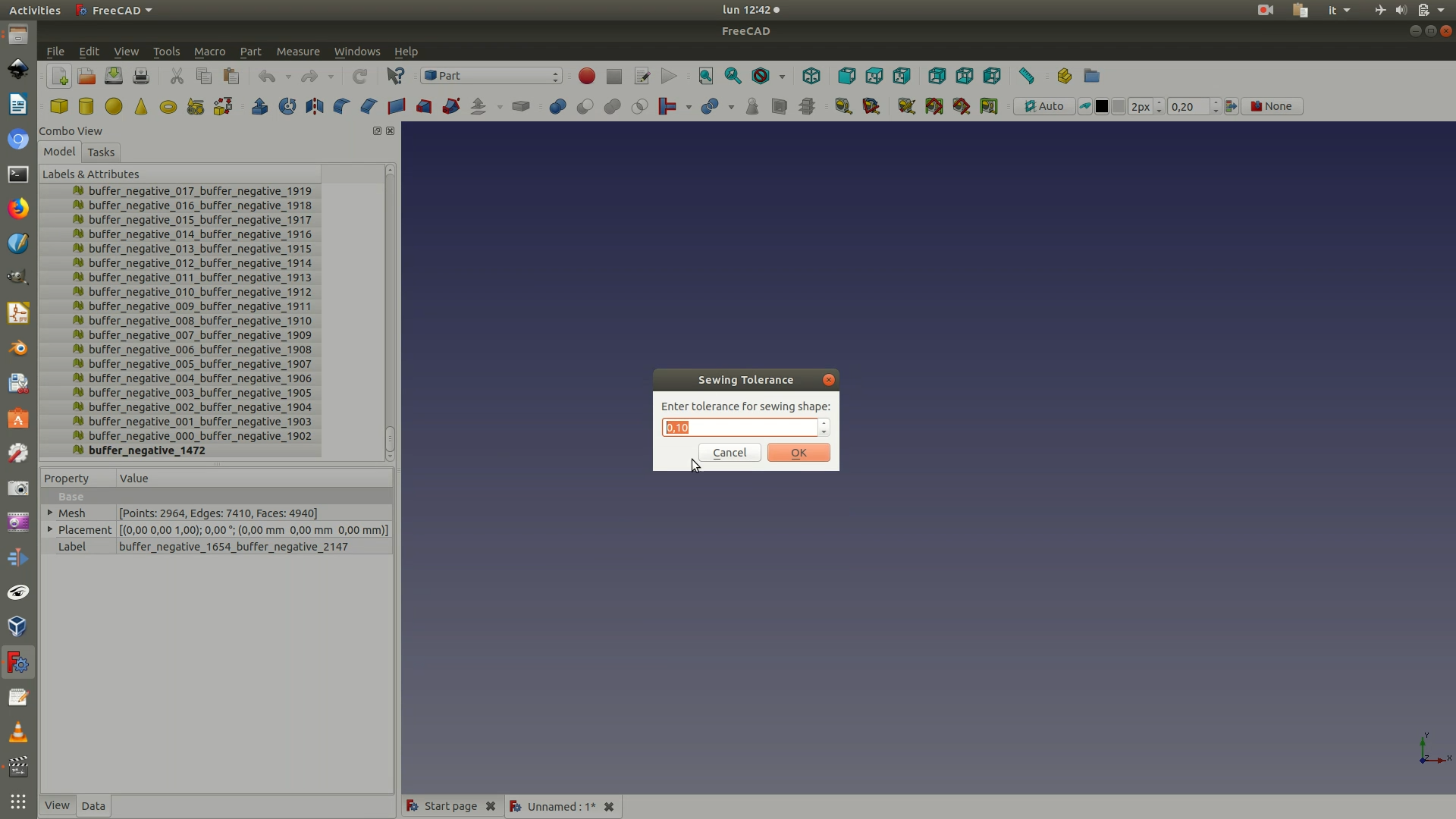
17. When the import is complete, you will see a series of elements on the left sidebar (names will vary depending on the name of the .shp files you first imported in Blender). These elements, while present on the sidebar, will not yet be visible in the view. Move to the Part Workbench. To make the elements visible, select them all from the left sidebar panel and click through Part > Create shape from mesh. A pop-up window will ask you to fill in a value for sewing tolerance. Leave the default option (0,10). The result will be a solid generated from the mesh you had exported from Blender. Without deselecting the previously selected elements, hit the delete key to remove all the Mesh elements from the left sidebar (they have a small greenish icon next to their name) and leave only the Shape elements (blue icon).
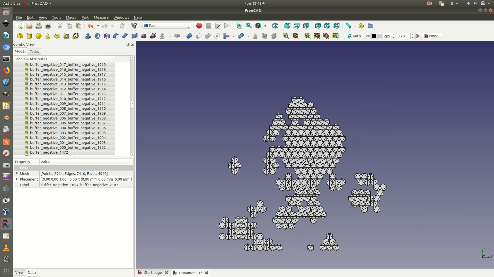
18. Now select all the Shape elements from the left sidebar and go through the menu Part > Refine shape. Wait a few seconds for the process to end. Without deselecting the previously selected elements, hit the delete key to remove all the older Shape elements from the left sidebar and leave only the new refined Shape elements.
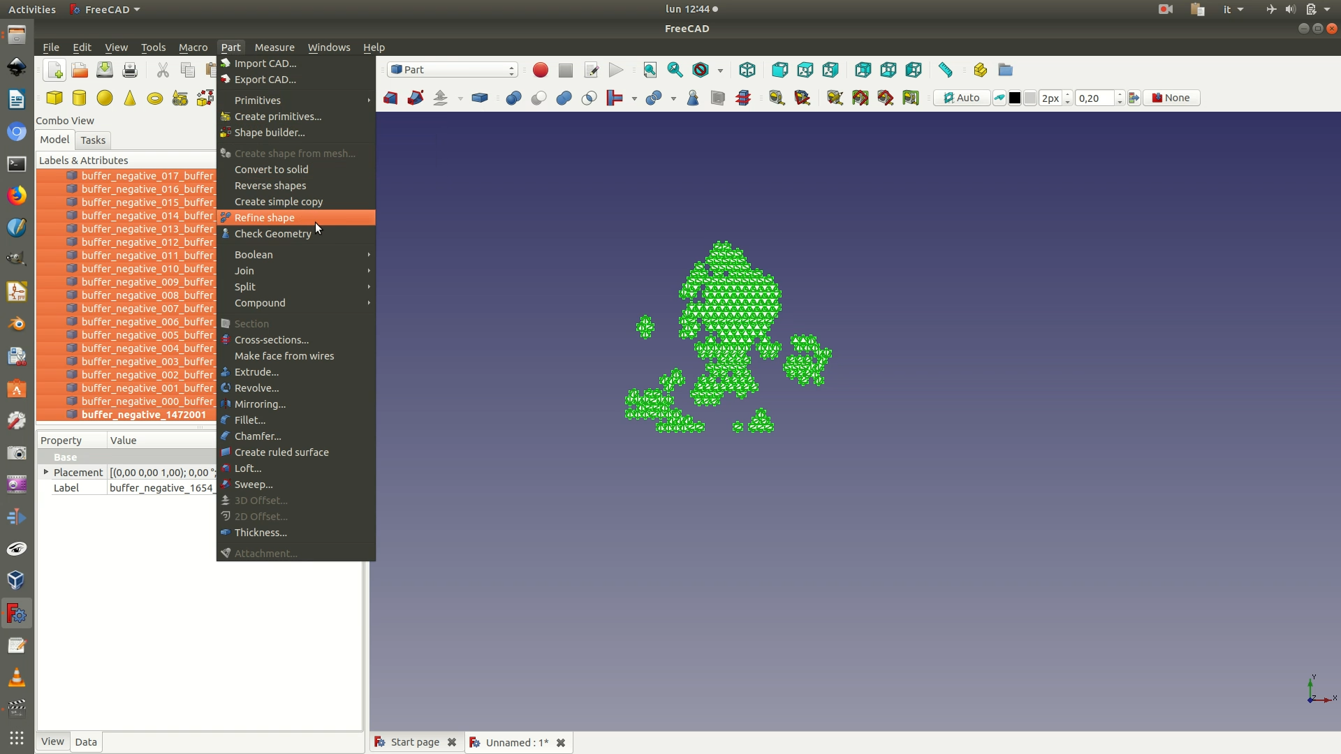
19. Now select all the refined Shape elements from the left sidebar and go through the menu Part > Convert to solid. Wait a few seconds for the process to end. Without deselecting the previously selected elements, hit the delete key to remove all the refined Shape elements from the left sidebar and leave only the new refined Shape elements - you’ll recognize them because they have the suffix (solid) appended at the end of the name. In practice, all these latter steps have left the shapes visually unchanged. What has been modified is the mathematical structure used to generate them, so that now they can be easily used for digital fabrication.
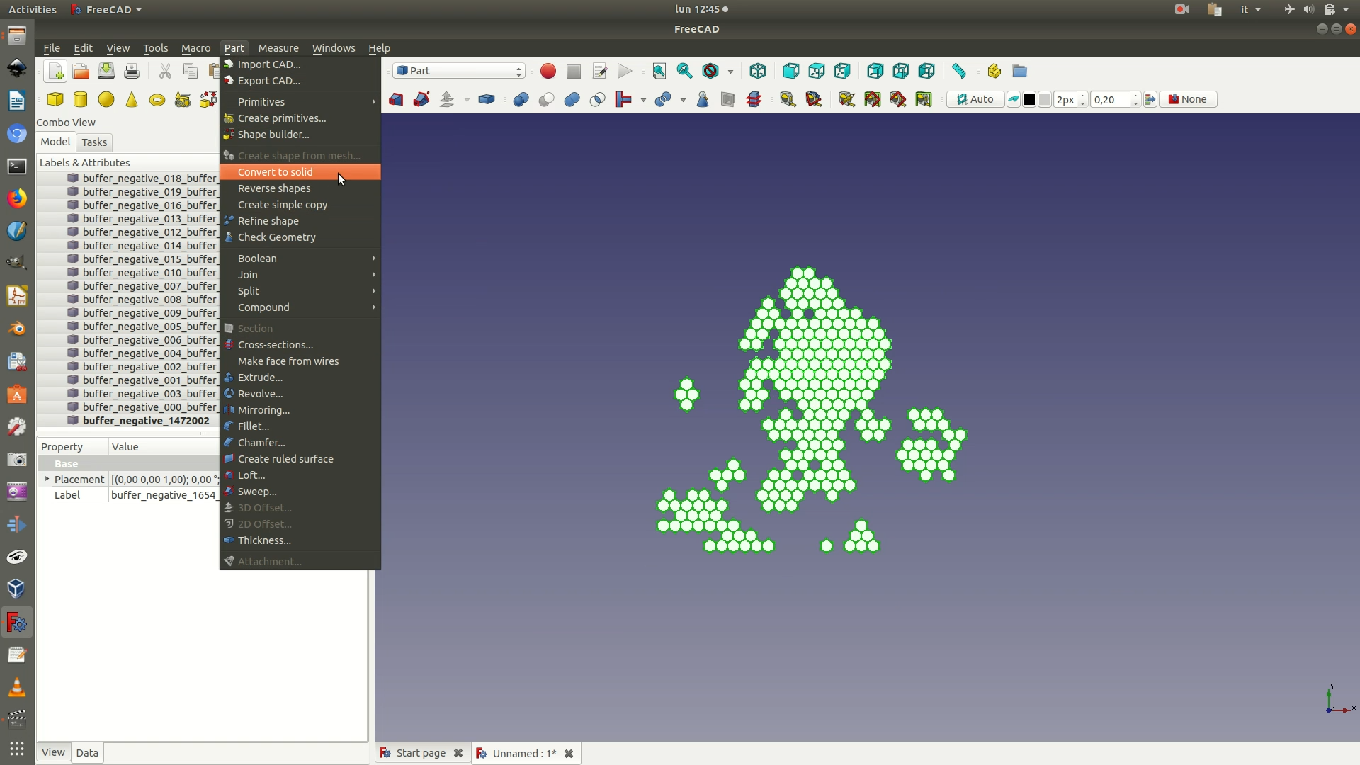
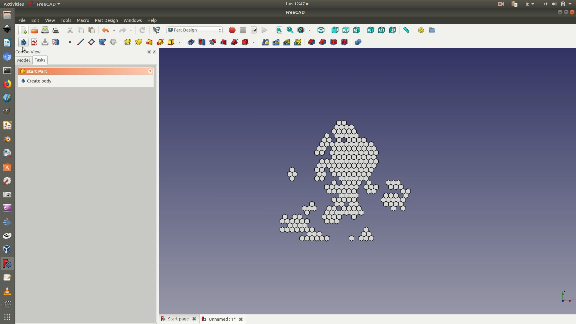
20. Switch to the Part Design workbench to create the base on which the hexagons will sit. Create a new body (the container for your design) and a new sketch (the 2D drawing of your object). To do this, first click through the menu Part Design > Create Body, then through Part Design > Create Sketch. Select the XY plane from the left sidebar menu.
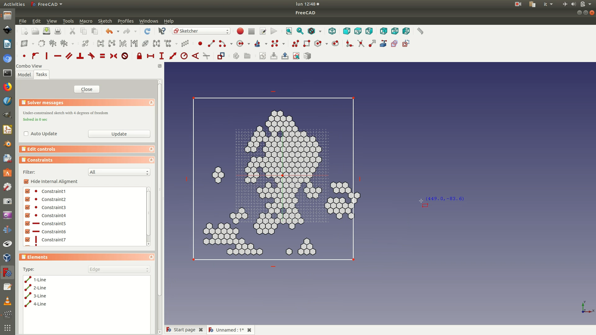
21. You should now have been directly redirected to sketch editing mode, or the Sketcher Workbench. Click through the menu Sketch > Sketcher Geometries > Create rectangle. You can now draw a rectangle/square similar to that in the image below. Don’t worry about dimensions, we'll fix them else further on.
22. Now select the top segment of the rectangle by clicking on it (selected elements turn green) and then apply the Horizontal Distance Constraint (Sketch > Sketcher constraints > Constrain horizontal distance). A pop-up window will prompt you to fill in the length value of the selected segment. Type in 500 mm (remember, the base is a 50x50cm block). At this point, you want to apply the Equality Constraint between this top segment and one of the side segments. This constraint forces the sides of the rectangle to be the same length as the top and bottom, and will result in your shape becoming a 50x50 cm square. To apply this constraint, select the top segment of the rectangle and the right side segment. Click through Sketch > Sketcher constraints > Constrain equal.
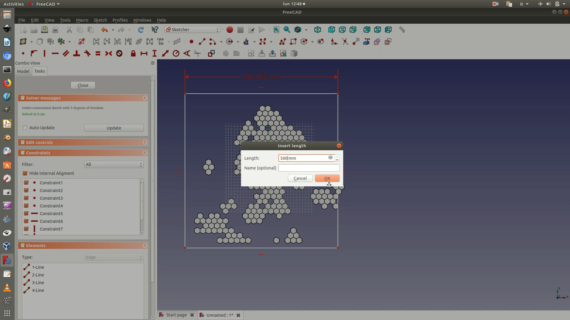
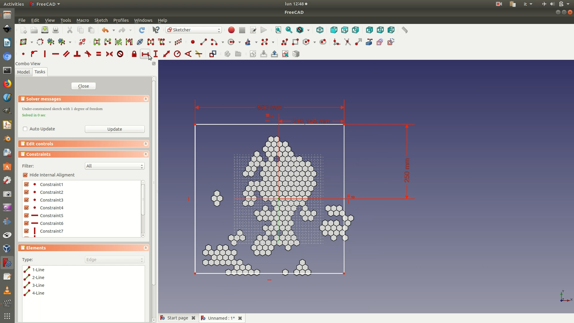
23. Position the square at the center of your plane. To do so, select the origin point and one of the corners of the square. Apply the Horizontal Distance Constraint and type in 250mm. Select the origin and corner of the square again, and now apply the Vertical Distance Constraint (Sketch > Sketcher constraints > Constrain horizontal distance). Type in 250mm in the pop-up window that appears. Close the Sketch.
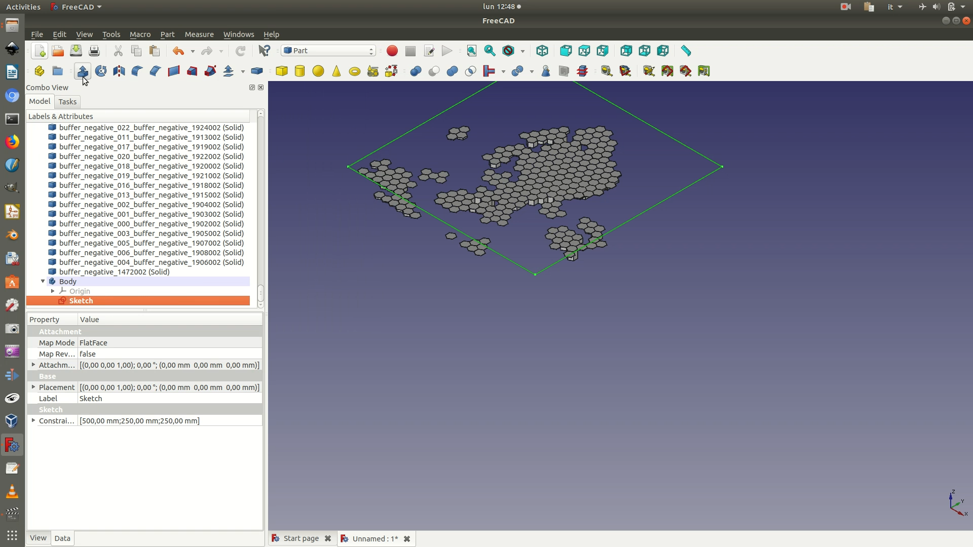
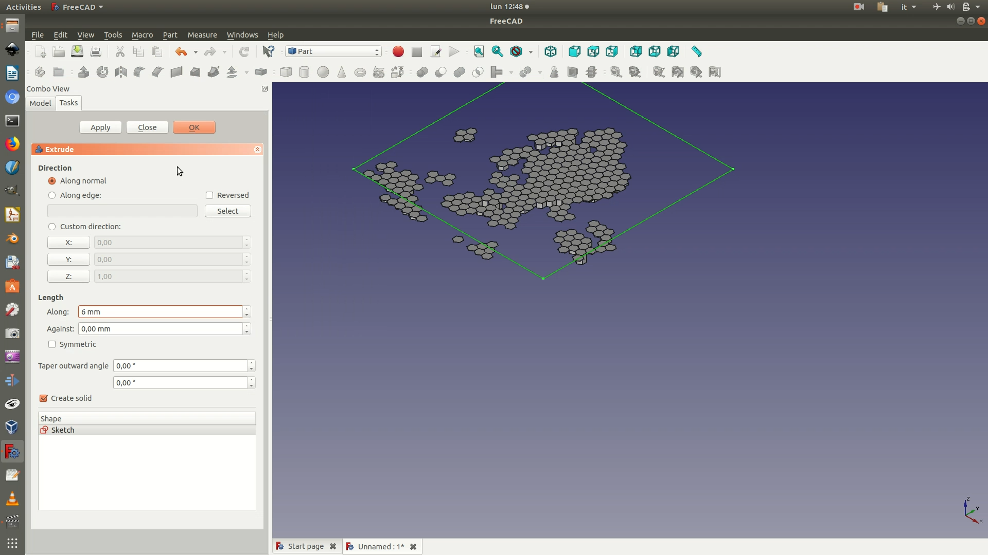
24. Select the sketch from the left side panel (see image below). Change to the Part Workbench. Go through the menu Part > Extrude. In the left panel you will be asked to type in a Length Along parameter. Fill it in with 6 mm (the height of the wooden sheet you will use as a support layer for the data + a minimal height of 3mm for the 3D printed layer of hexagons). Leave the other parameters as they are and click OK.
25. Change view by going through View > Standard Views > Front. Select the Extrude element from the left side panel. Navigate to the Data menu at the bottom of the left panel sidebar. Go to the Placement > Position > Z and increase/decrease the value until its sits right below the hexagonal polygon objects (in our case, we had to use a value of -26.5 mm).
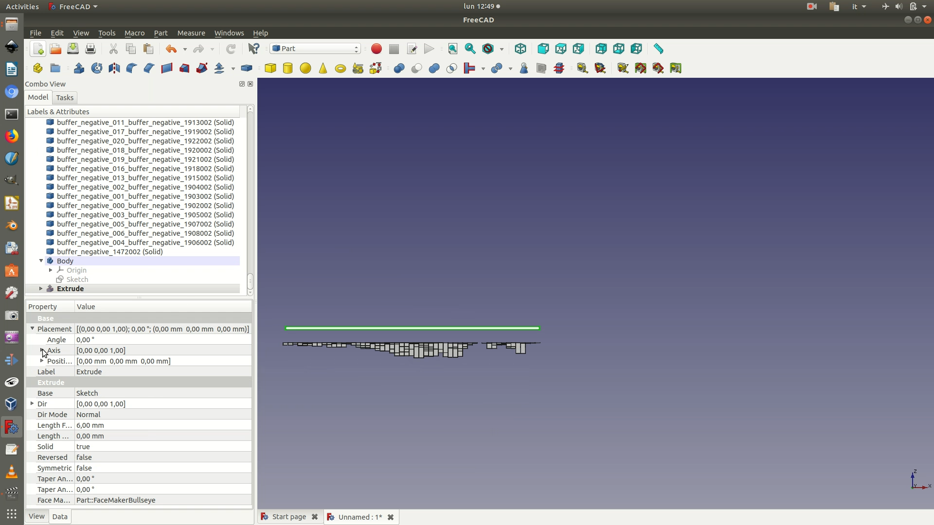
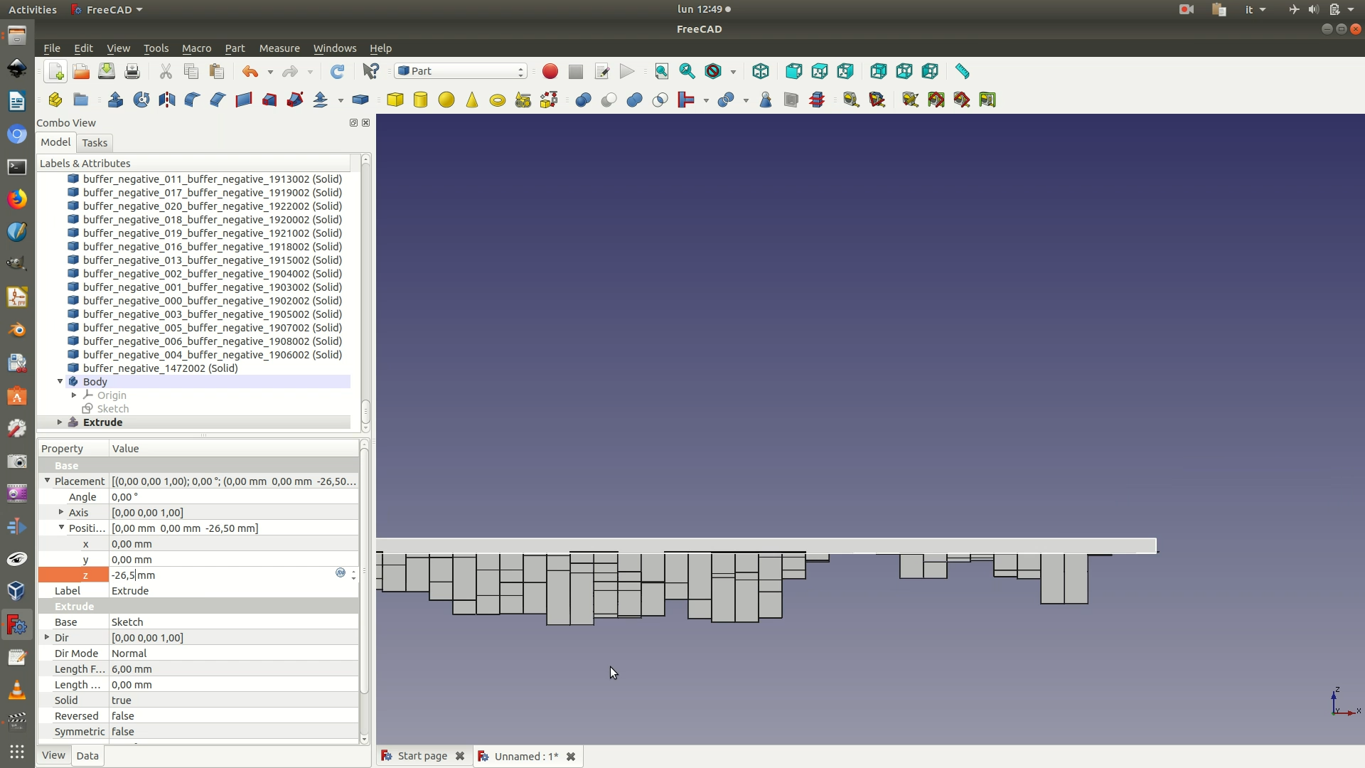
26. From the left sidebar select both the square base and the 3D hexagon solids. Click through Part > Boolean > Union. This might take a bit, depending on your CPU. You will now have a single Fusion element in your left sidebar, grouping all the other elements.
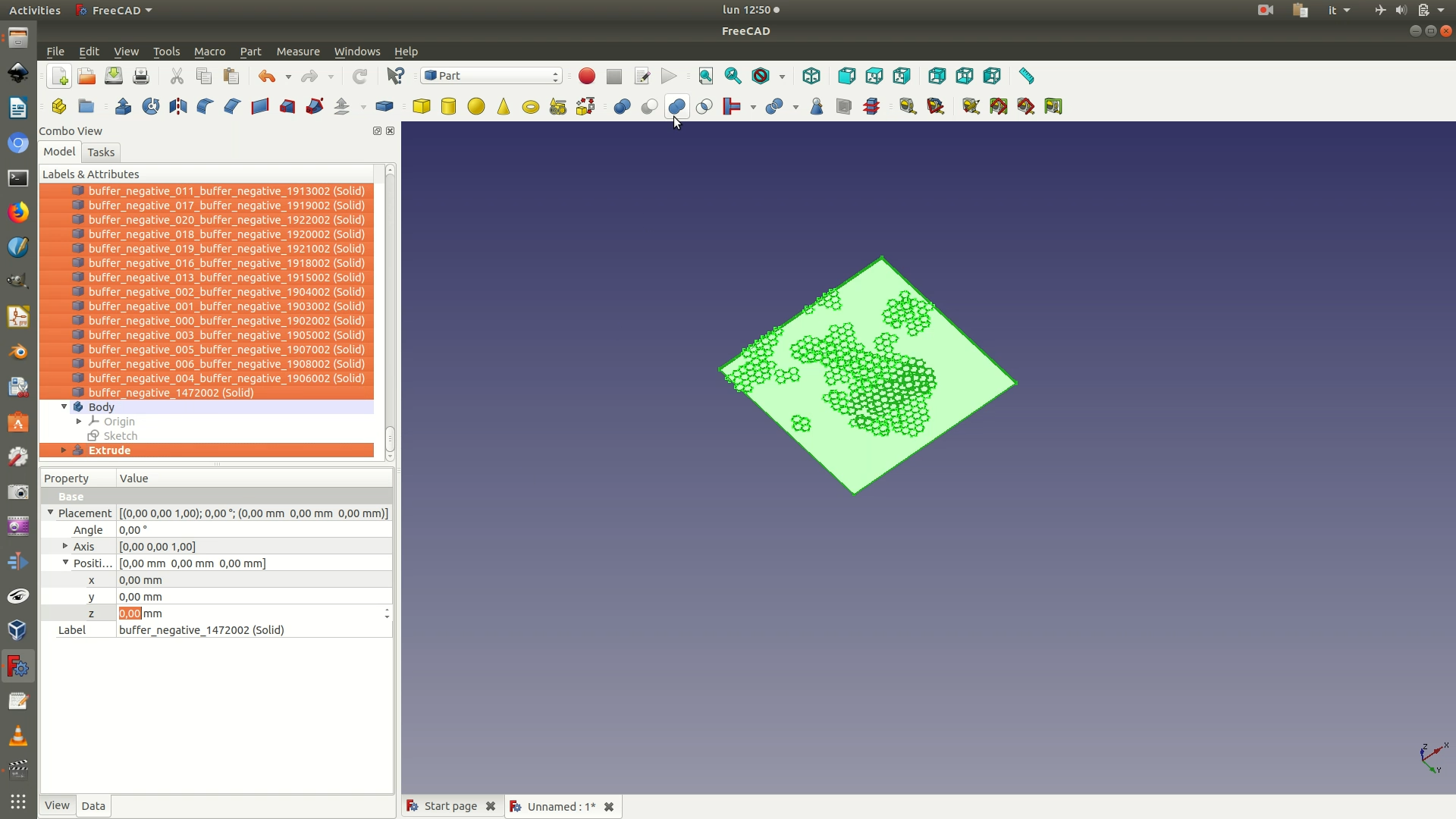
27. Move to the Part Design workbench. Select the Fusion element and click on Part Design > New body. This will create a new container body element that uses the selected Fusion element as base.
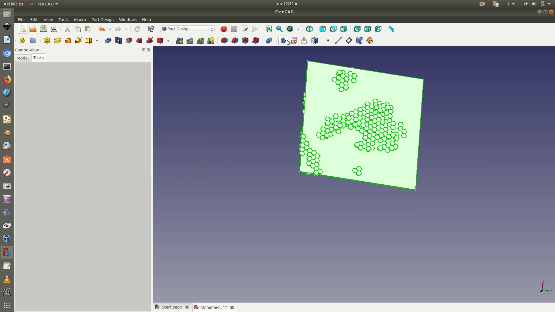
28. Click on the top face of the object from the 3D view to select it. Then go through the menu Part Design > New Sketch. This will create a new sketch on top of the face you had selected.
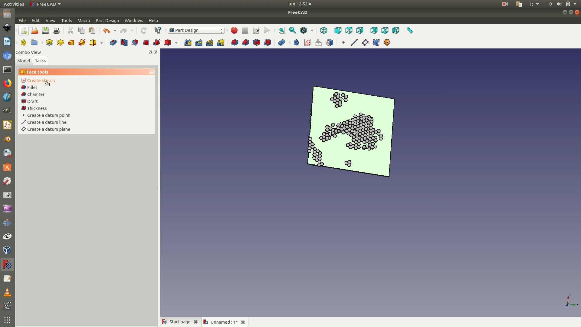
29. As you can see, some hexagonal polygons overflow the boundaries of the 50x50 cm square base, and we need to cut them out. Go through the menu Sketch > Sketcher geometries > External geometry. Then click on the top and bottom segments of the base square to select them. This will import the selected segments as guidelines in the sketch. Now click on Sketch > Sketcher geometries > Rectangle and draw a square as big as the square base of your object. Then draw another square or rectangle; the dimensions don’t matter as long as it is bigger than the hexagon layer (see image below). Close the sketch. Go through the menu Part Design > Pocket. Fill in the following options on the left menu that appears:
Type > Through allSymmetric to plane: checkbox checked
Click OK to apply the Pocket command. The hexagonal solids will now be clipped to the margins of the 50x50 cm square.
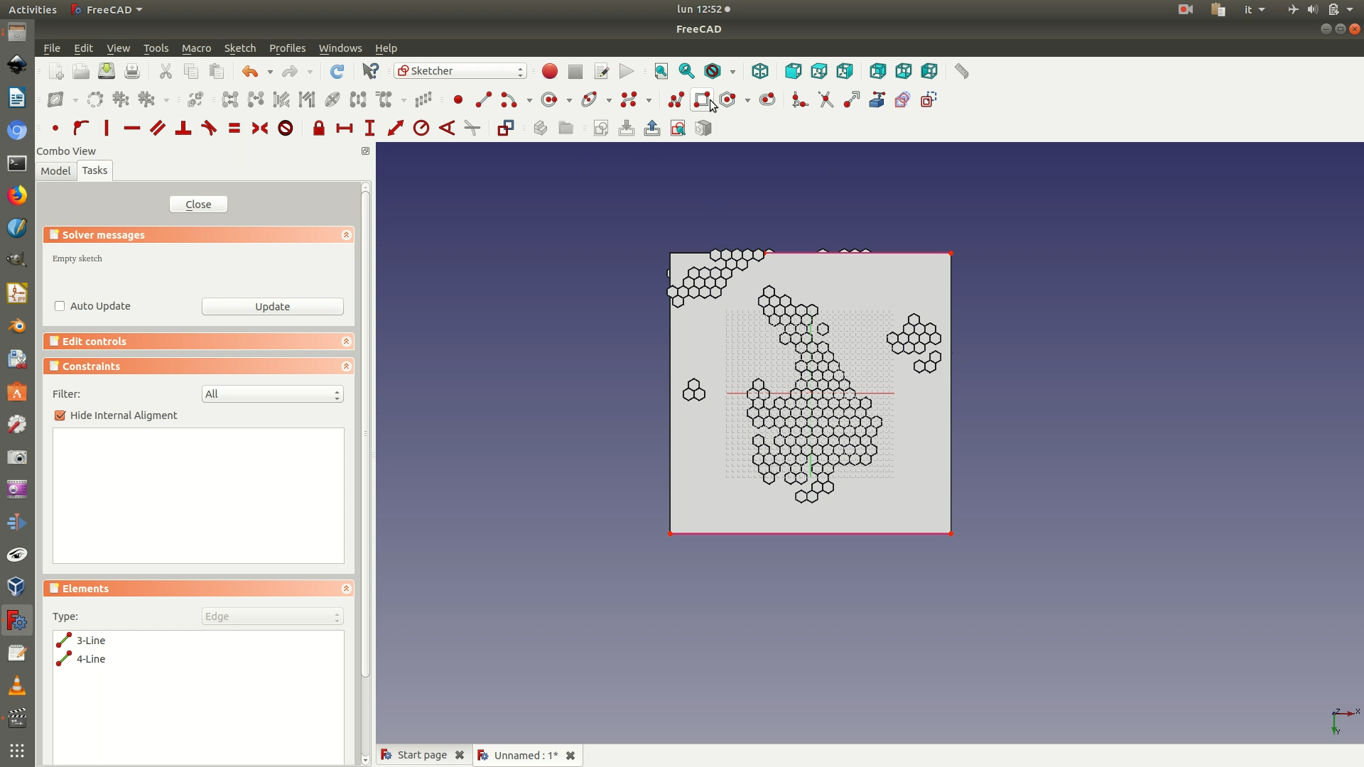
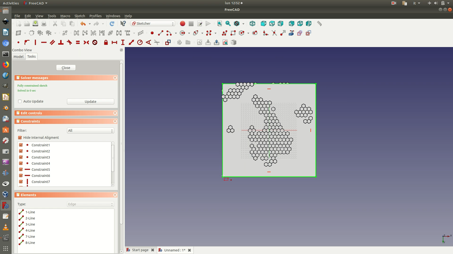
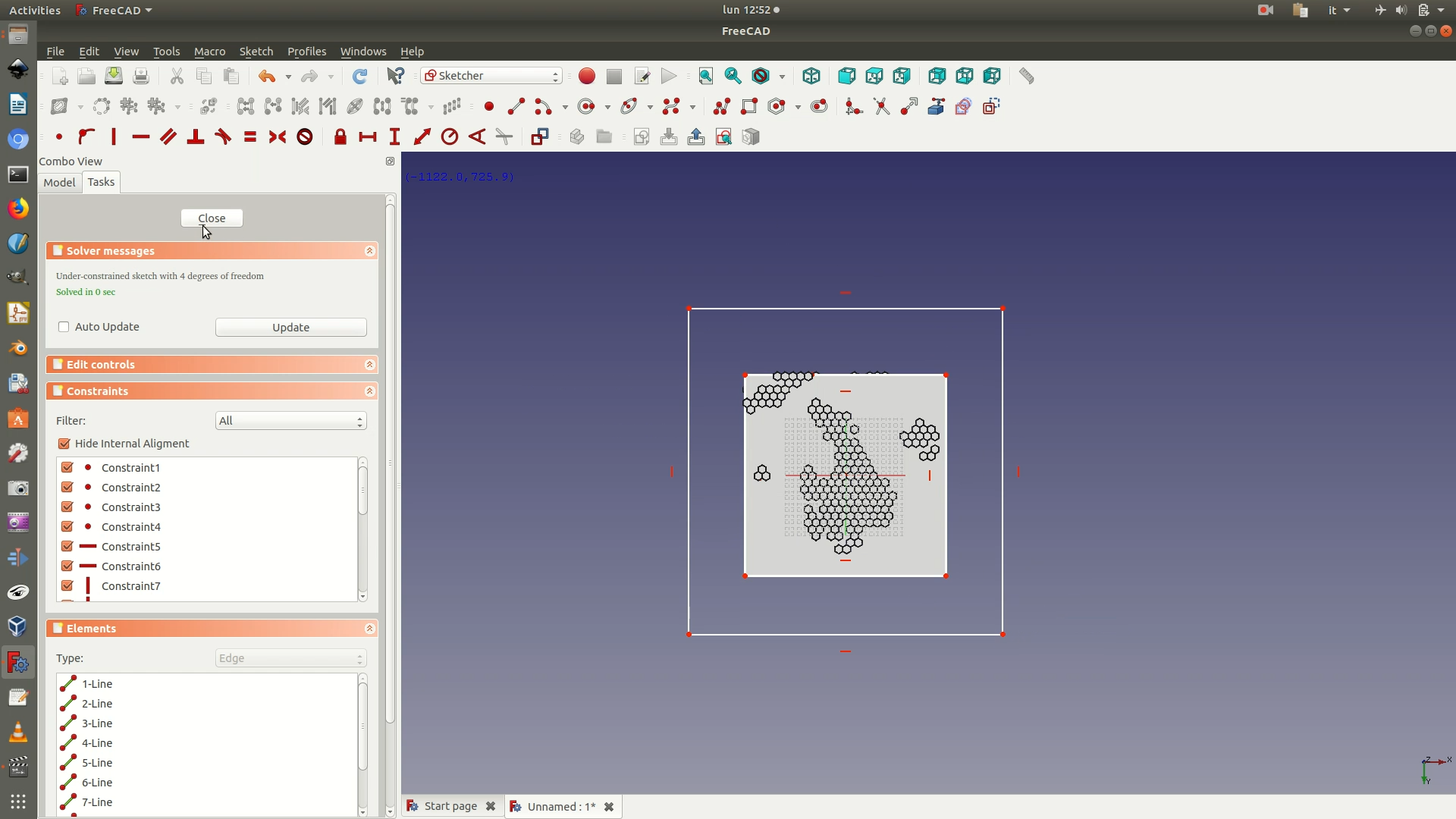
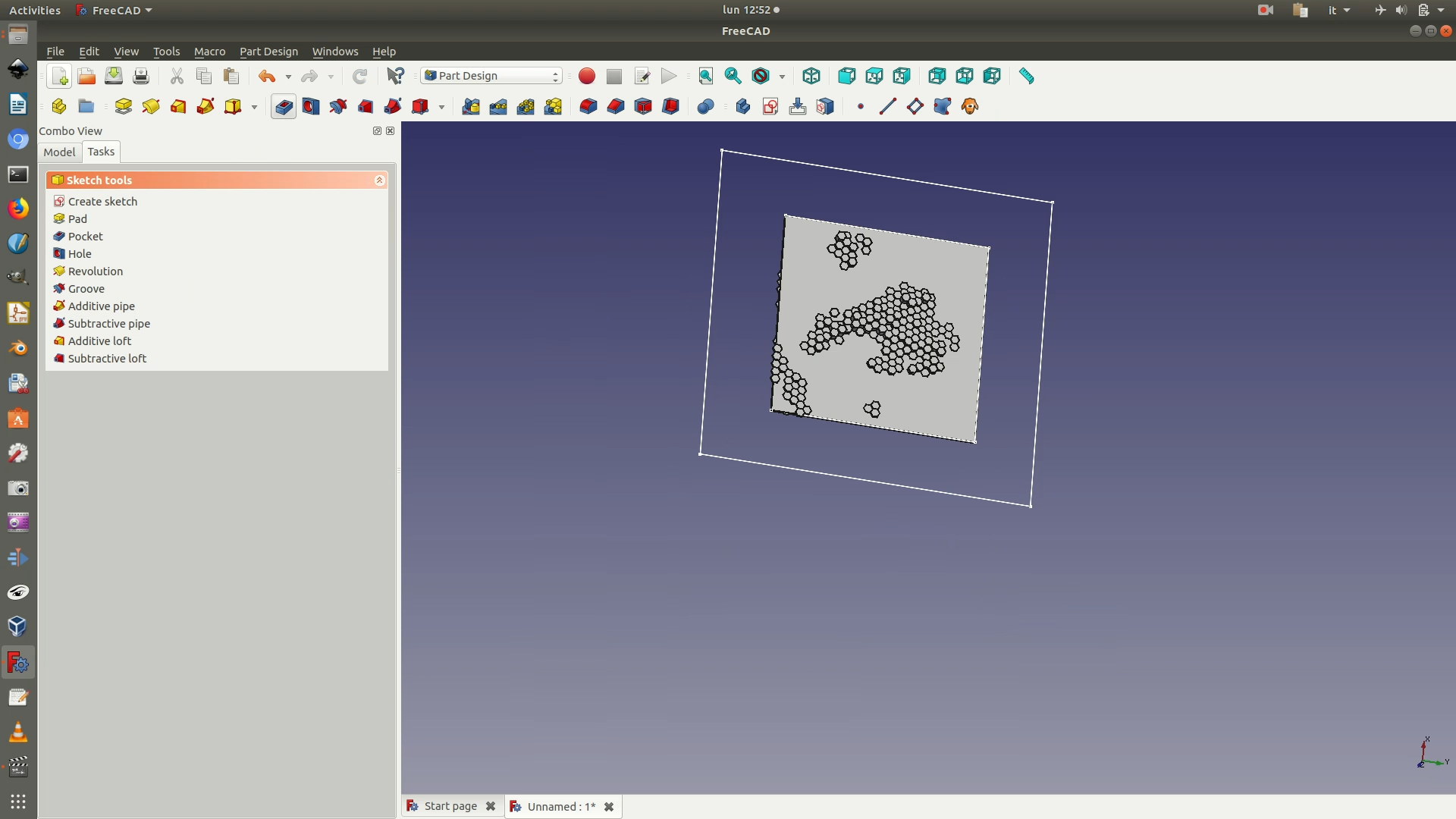
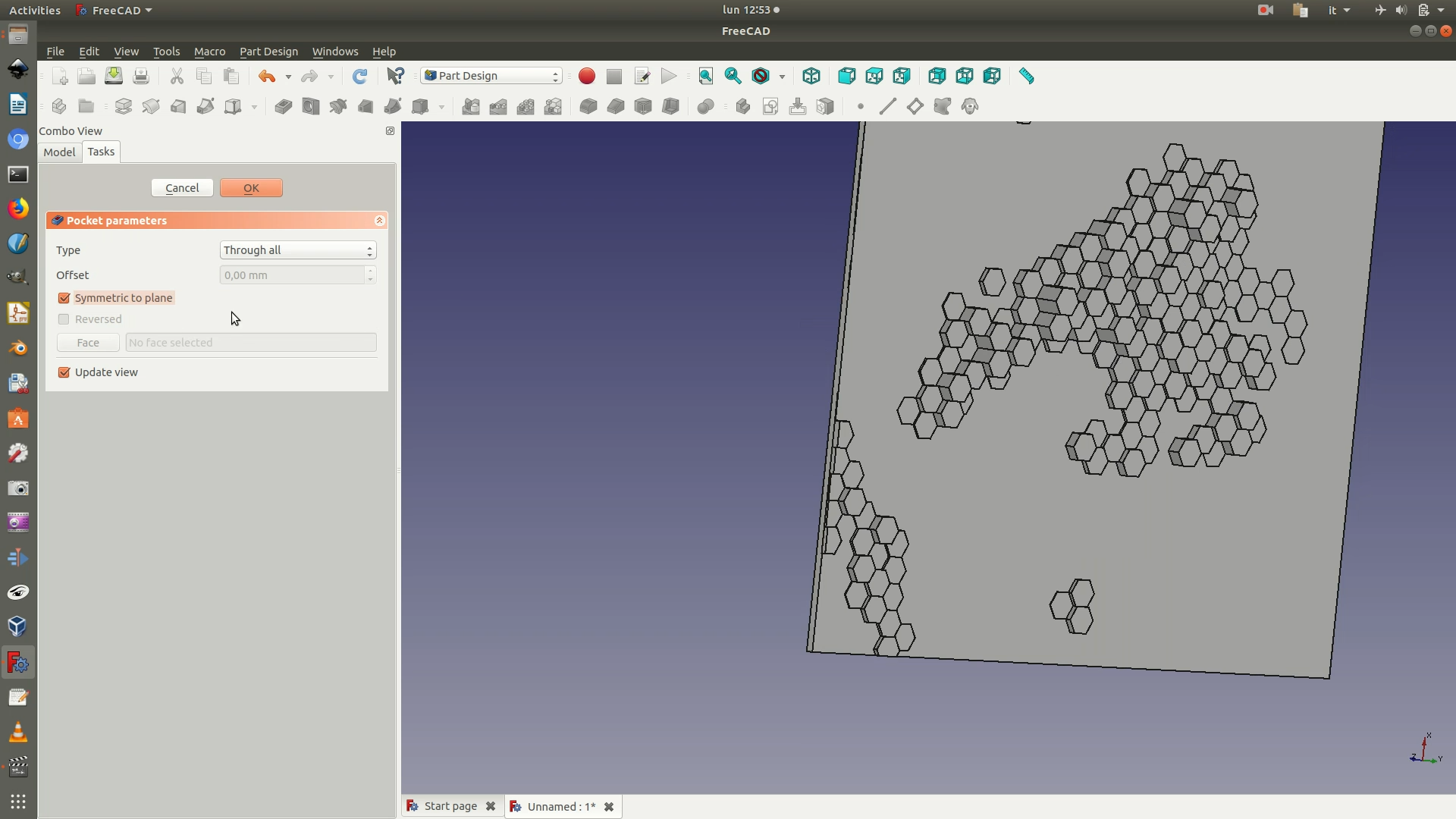
30. Select the last Body element from the left sidebar, the one containing this last object created. Go through File > Export. Select .STL as the file type and export your project.
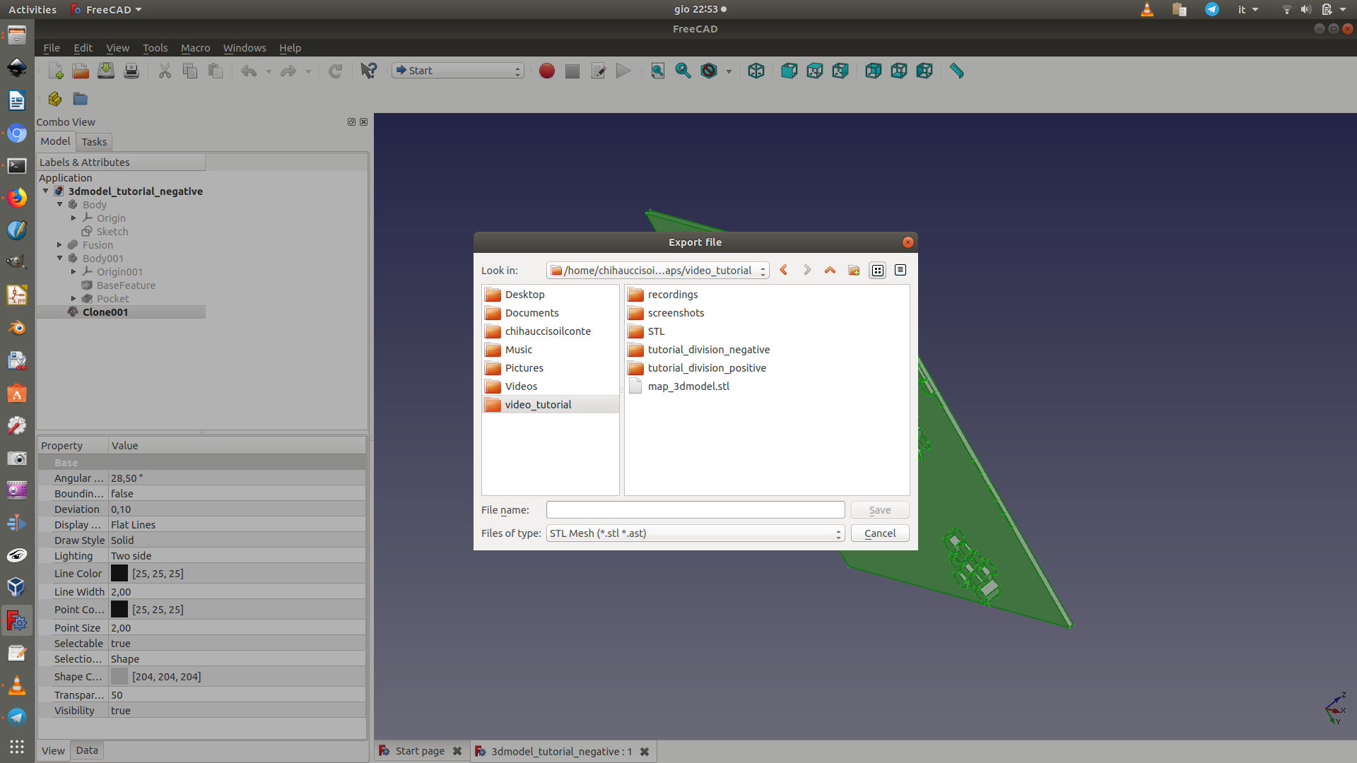
31. Repeat steps 16 - 30 with the second data layer (the one with positive values).
