3D Modeling · 3D Data Map
Part 5 - The legend
Full Video Tutorial
Workflow explanations
Download final 3D modeling files
1. Of the two .blend files containing the hexagon mesh with either positive or negative values, choose the one containing the biggest absolute value (you would know this by looking at the data in your spreadsheet or QGIS attribute table). Open the file with Blender. Note that you need a mouse to work with Blender. Press the Z key to switch to Wireframe mode. In this visualization mode, the polygons become transparent and so you can see the map below to match their position. Activate the front view by pressing the 1 key on your keyboard.

2. Select the tallest of the hexagon solids (the one with the biggest absolute value) and copy-paste it somewhere else in the layout, preferably further away from the other solids so that you don’t confuse it. Select all the other solids except this last one and make them not selectable and hidden from view by clicking the eye icon and the cursor icon in the right-hand panel.

3. Copy-paste the previously duplicated solid hexagon another time. Select this new copy and scale it to half the height of the original by going on the right Transform menu and on the Dimension box replace the value for Z with half the current value.
Note: to make things confusing, there is a Transform menu also on the right, which however contains different commands.

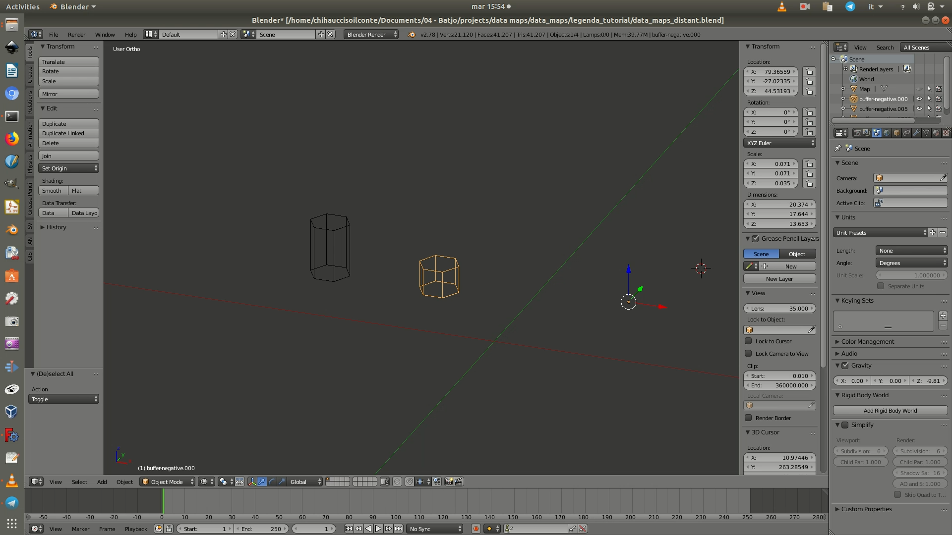
4. Select the first of the copied hexagon solids and copy it a second time. Select this new copy and scale it so that it proportionally represents the minimum absolute value of the dataset, in our case 1. To do so, go on the right Transform menu and on the Dimension box replace the value for Z with the value corresponding to: the current value divided by the actual max. absolute value in your dataset. You will now have three 3D hexagons: one representing the max. value, one representing the middle value, and one representing the min. value. You can of course tweak this as you wish, for example by having the middle hexagon representing the mean, median, or mode.
Note that the Z values of the heights might not correspond to the data value they represent: this because when you had created the 3D model of the grid, you had scaled it to fit into the 50x50 cm base.
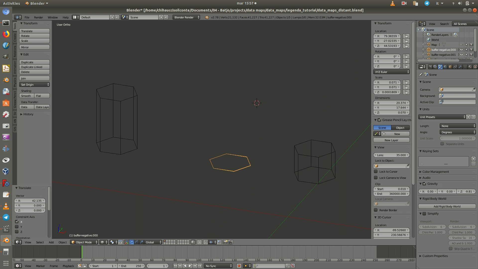
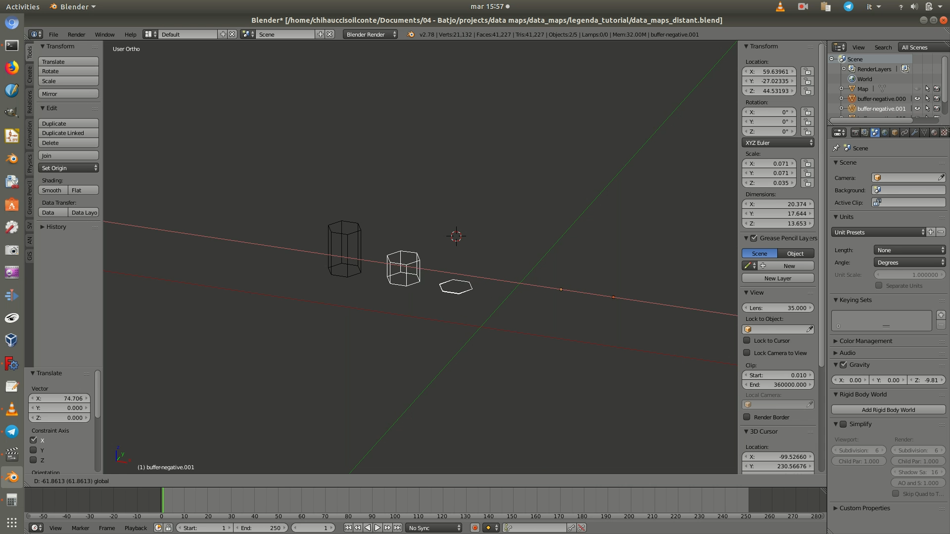
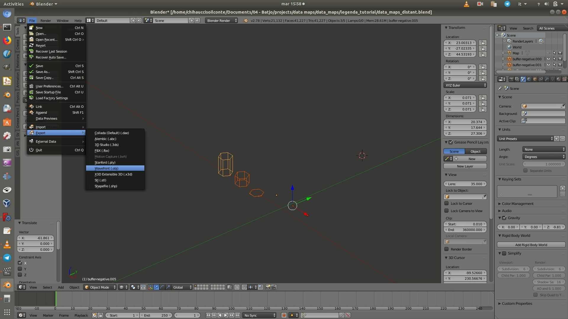
5. Select these three hexagonal solids and go through File > Export > Wavefront (.obj). When the save as window opens up, there will be a few options on the left panel. Leave everything with the default values, except:
Up: chooseZ UpSelection only: checkbox checked
Then click on Export obj from the top right corner.
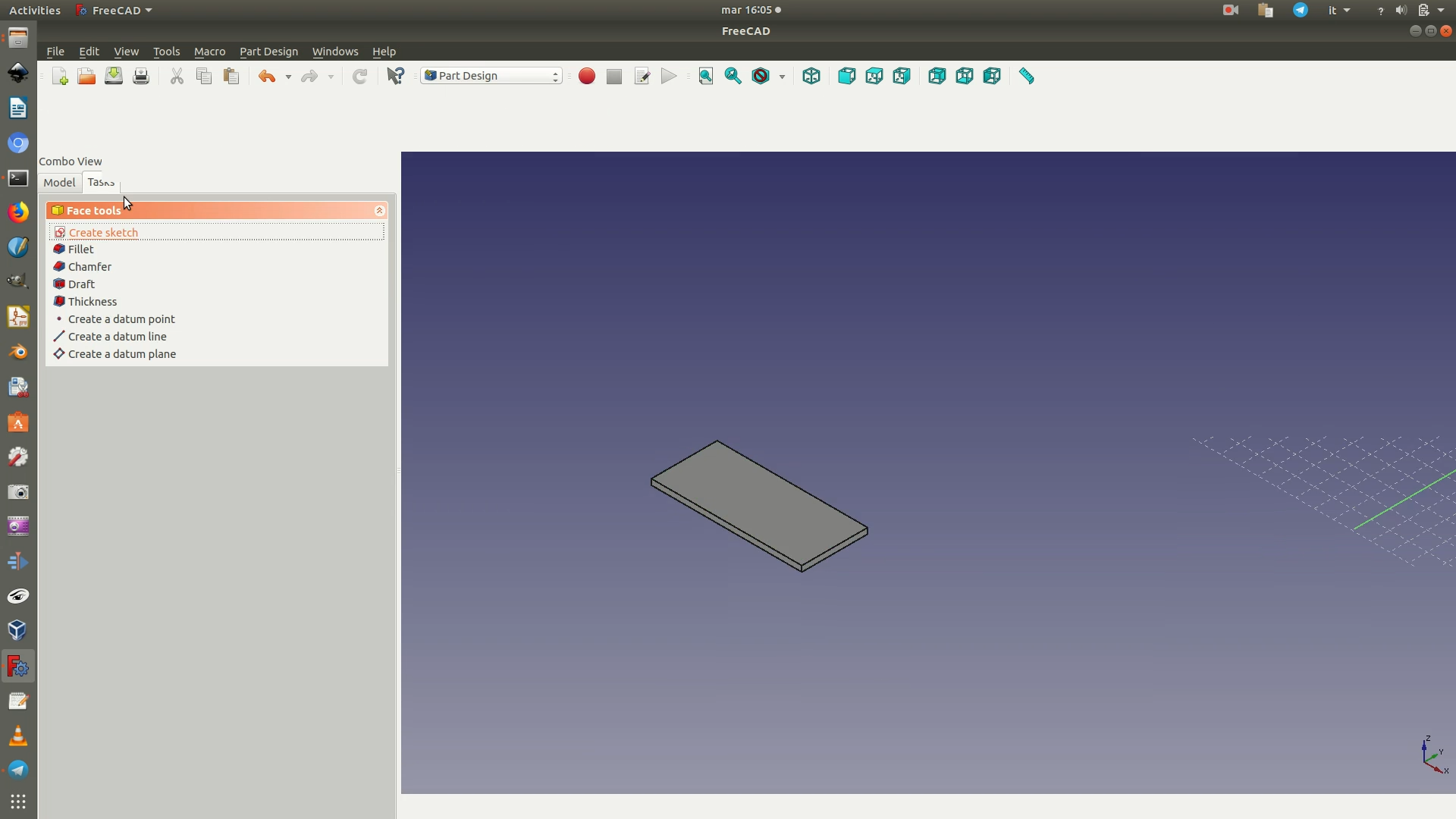
6. Make a duplicate of the file containing the grid support for the data layer (see previous section of the tutorial to download it) and open it in FreeCAD. Switch to the Part Design workbench. Click on the last Body element so that it is selected (highlighted in green) and go through the menu Part Design > New body. Click on the top face of the grid object from the 3D view to select it. Then go through the menu Part Design > New Sketch. This will create a new sketch on top of the face you had selected.
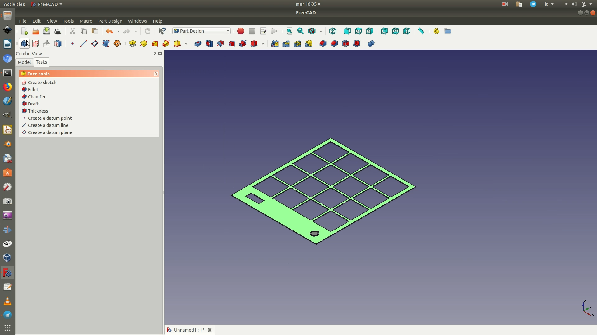
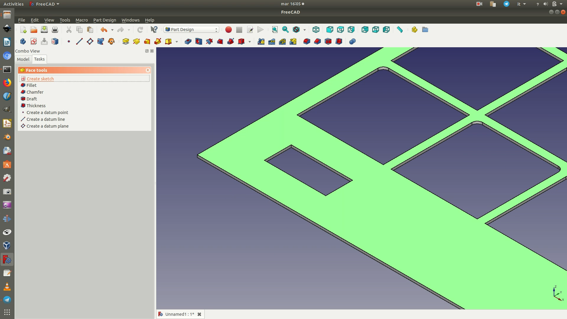
7. Go through the menu Sketch > Sketcher geometries > External geometry. Then click on the top and bottom segments of the slot where the legend will be placed (see image below). This will import the selected segments as guidelines in the sketch. Now click on Sketch > Sketcher geometries > Rectangle and draw a rectangle as big as the slot (using the purple lines as guidelines). Close the sketch.
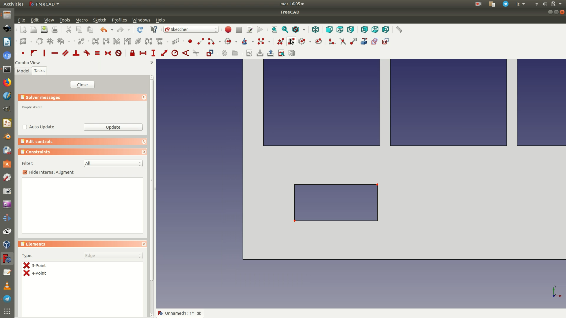
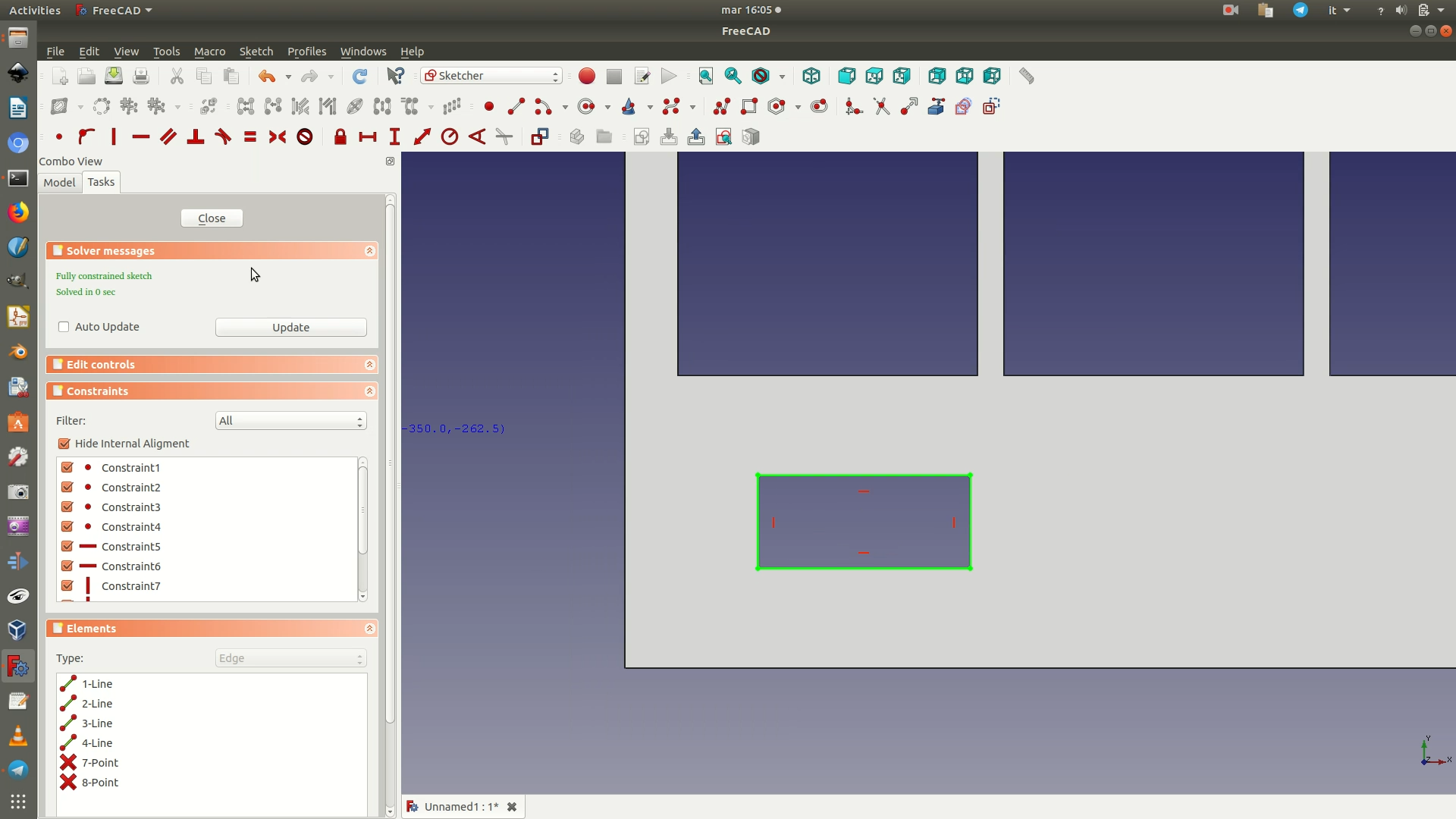
8. Switch to the Part workbench. Go through the menu Part > Extrude. In the left panel, set the following values:
Custom direction > Z: -1Length Along:3 mm(the height of the wooden sheet you will use as a support layer for the data)
Leave the other parameters as they are and click OK.
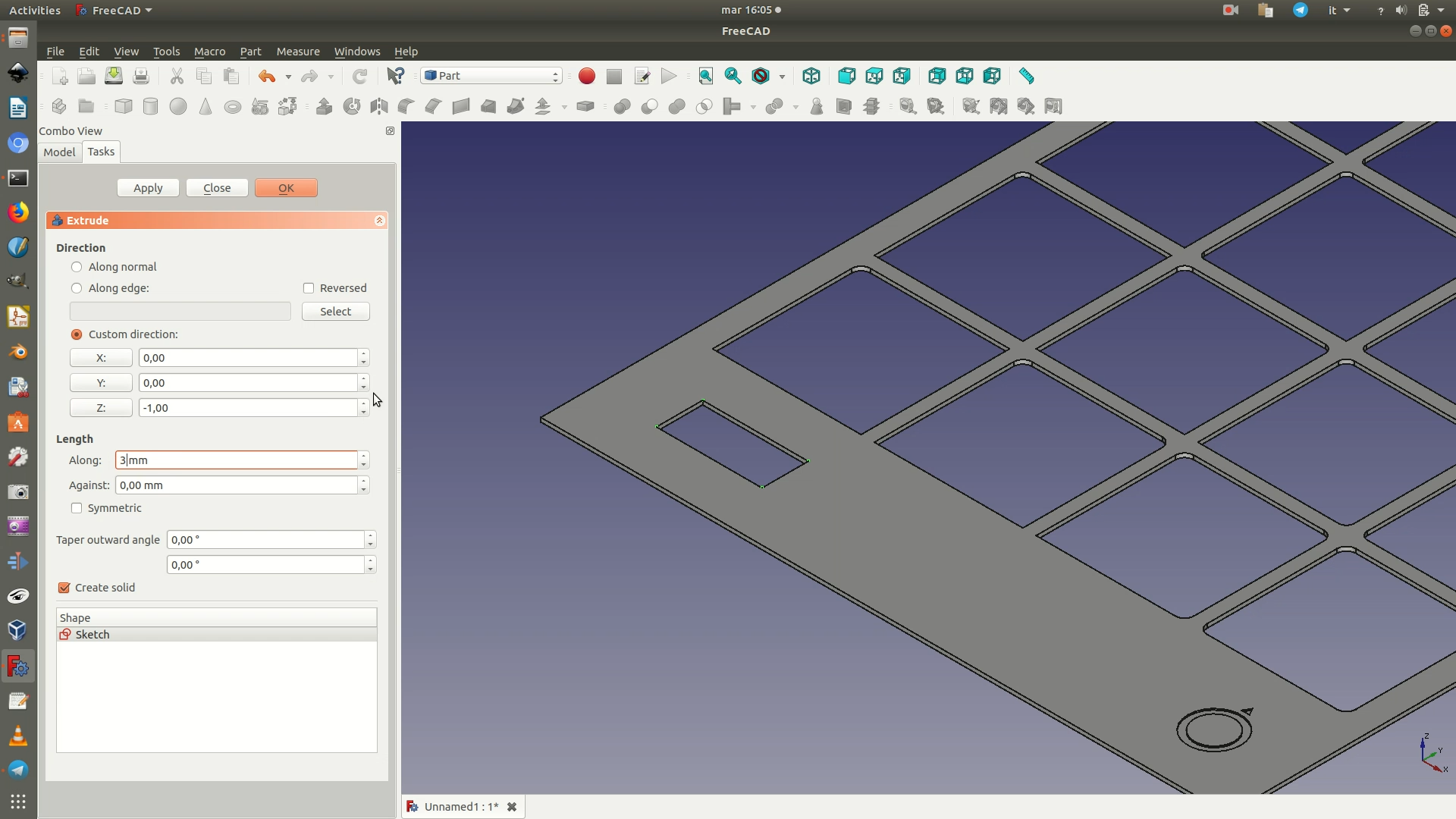
9. Select the last Body element containing the data support grid and hide it from view by hitting the spacebar. Select the rectangle that you have extruded in the previous step, which should now be the only visible object. Switch to the Part Design workbench. Go through the menu Part Design > New body. Click on the top face of the rectangle and go through the menu Part Design > New Sketch. This will create a new sketch on top of the face you had selected. Go through the menu Sketch > Sketcher geometries > External geometry. Then click on the left and right edges of the rectangle. This will import the selected segments as guidelines in the sketch. Now click on Sketch > Sketcher geometries > Rectangle and draw a rectangle bigger than the base rectangle. Select the top left corner of the big rectangle and the top left corner of the smaller base rectangle. Apply a Vertical Distance Constraint (Sketch > Sketcher constraints > Constrain vertical distance) with a value 5mm. Select the same two corners and now apply a Horizontal Distance Constraint (Sketch > Sketcher constraints > Constrain horizontal distance) with a value 5mm. Apply both the vertical and horizontal distance constraints, with the same value of 5mm also between the bottom right corner of the big rectangle and the bottom right corner of the smaller base rectangle. Close the sketch.
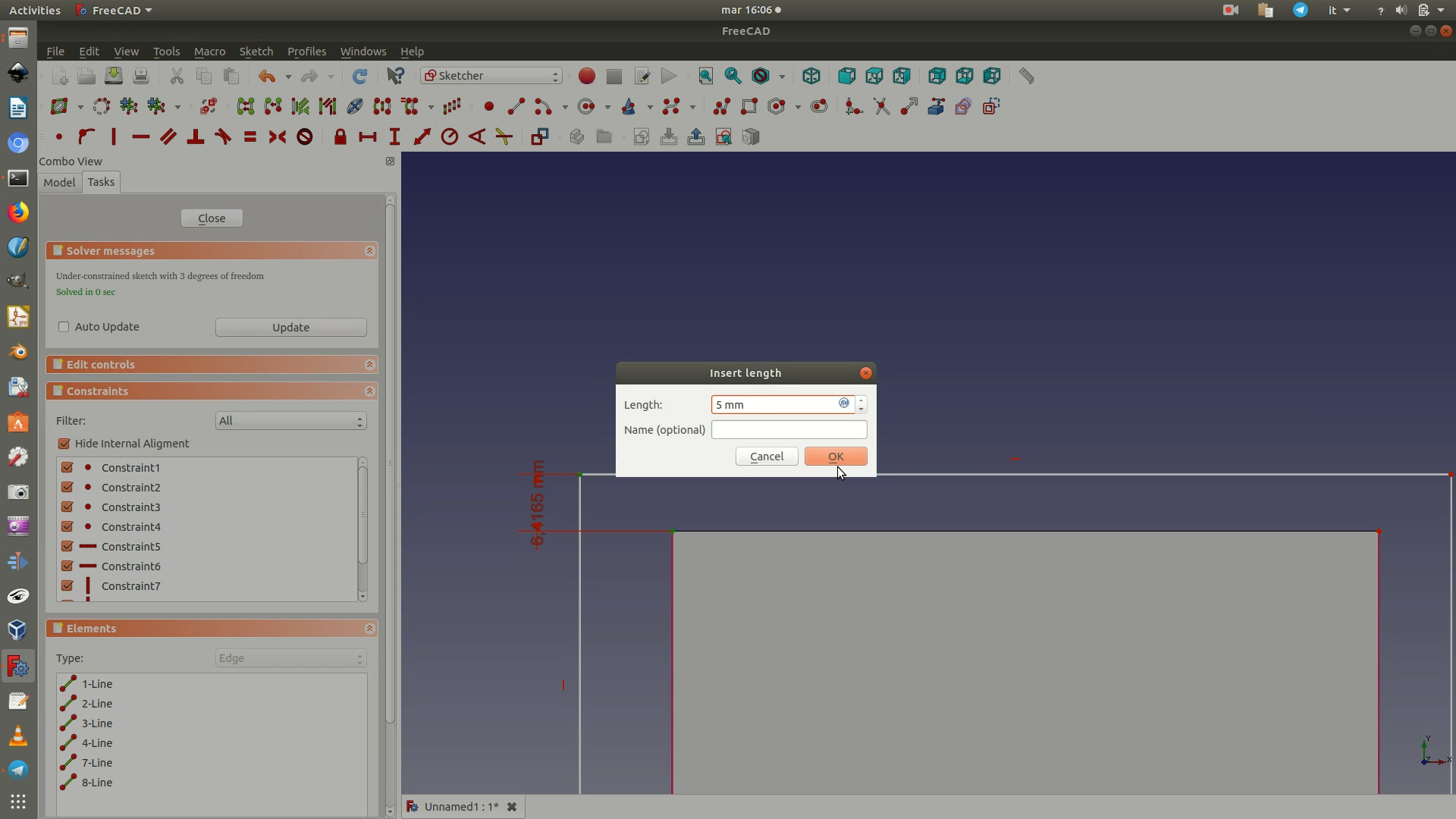
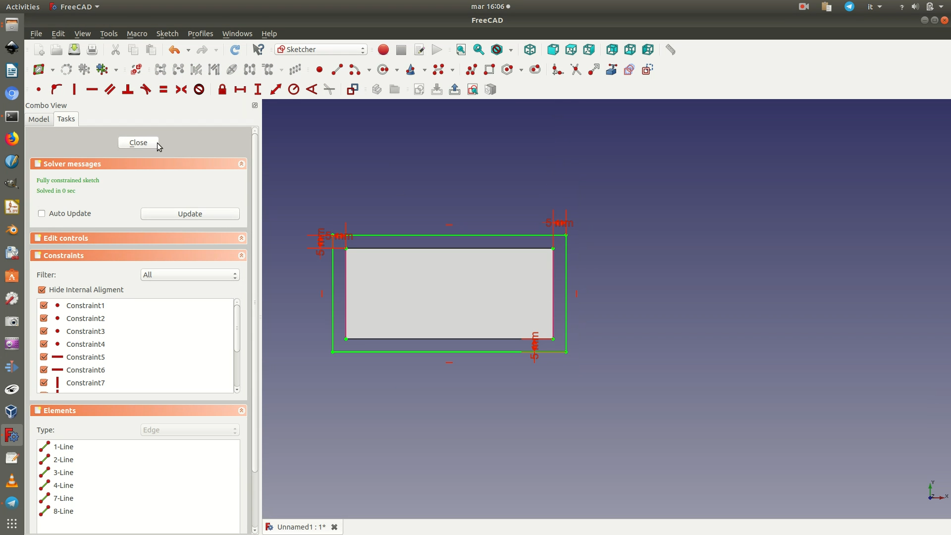
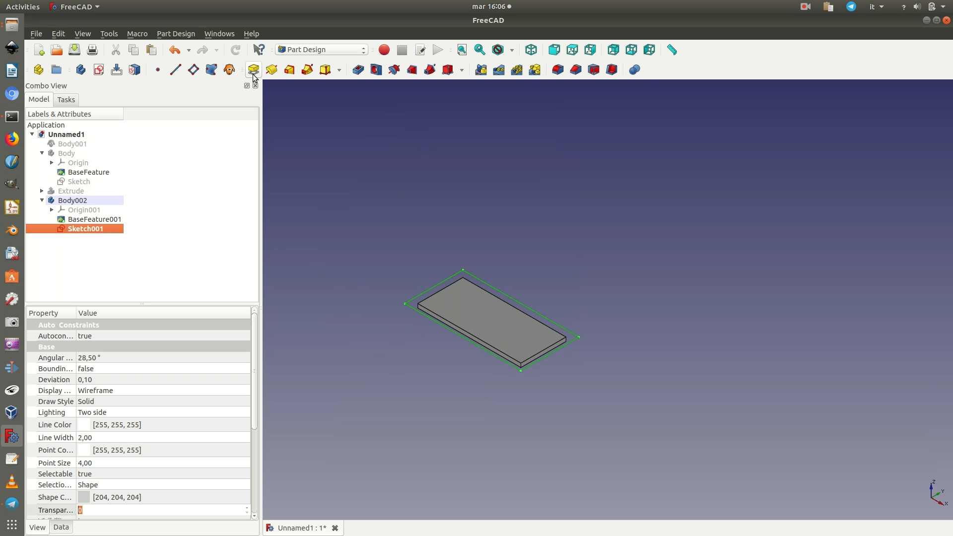
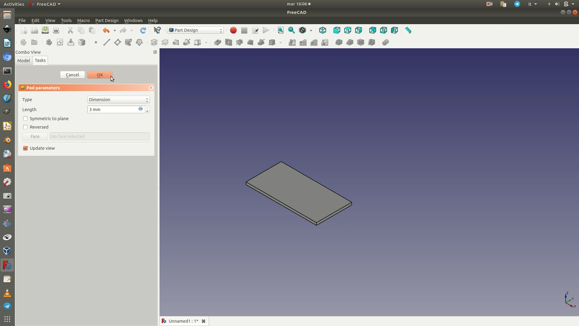
10. Select the sketch from the left sidebar and go through Part Design > Pad. On the left side parameters panel, set a Length of 3mm.
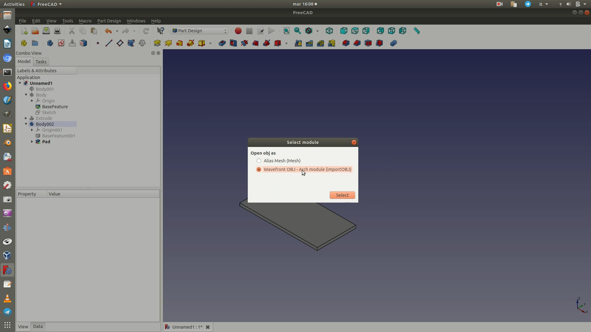
11. Import the three hexagonal polygons you had created in Blender, by going through File > Import. In the select module that appears, select Wavefront OBJ - Arch module (importOBJ).
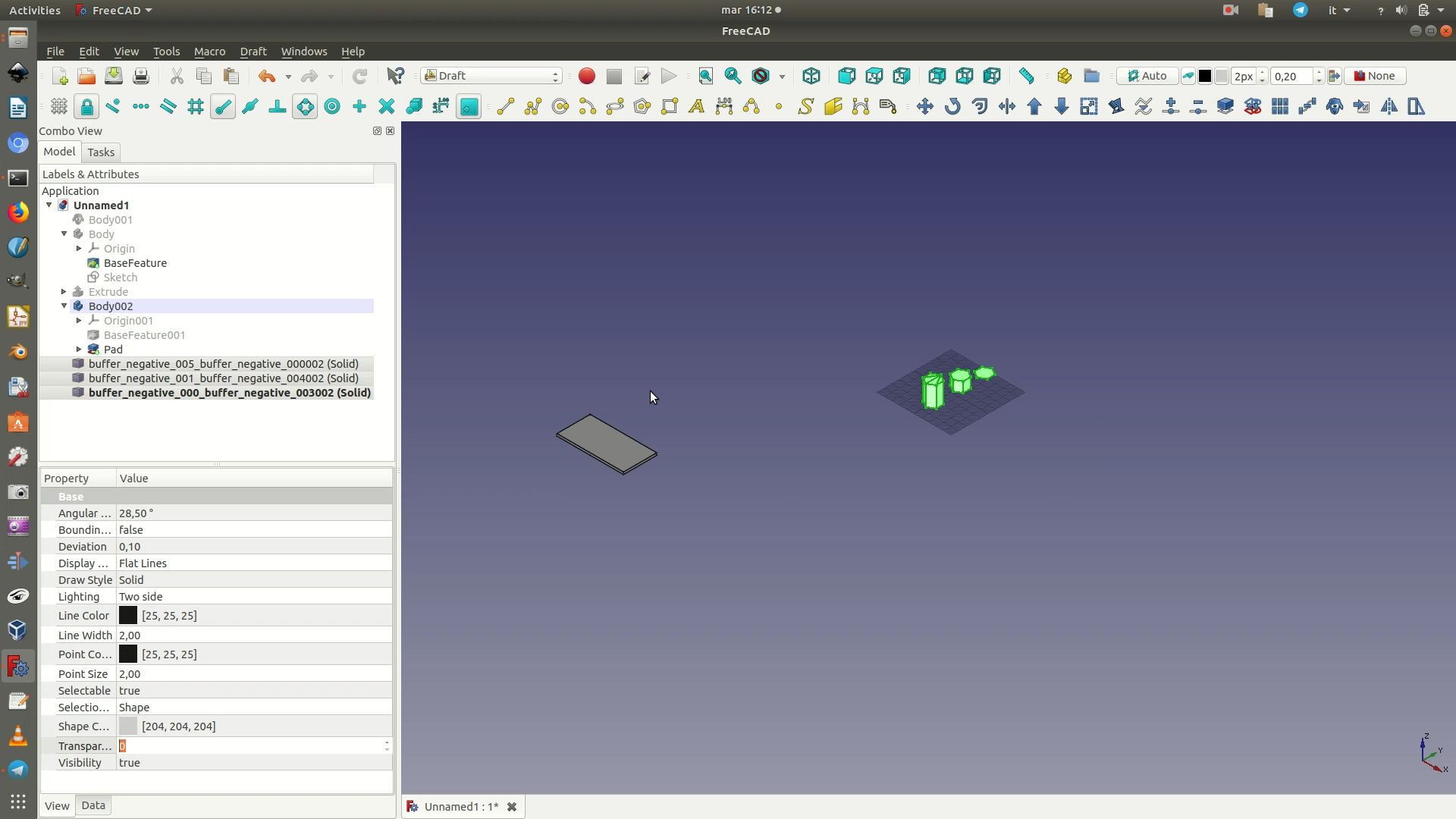
12. When the import is complete, you will see a series of elements on the left sidebar (names will vary depending on the name of the .shp files you first imported in Blender). These elements, while present on the sidebar, will not yet be visible in the view. Move to the Part Workbench. To make the elements visible, select them all from the left sidebar panel and click through Part > Create shape from mesh. A pop-up window will ask you to fill in a value for sewing tolerance. Leave the default option (0,10). The result will be a solid generated from the mesh you had exported from Blender. Without deselecting the previously selected elements, hit the delete key to remove all the Mesh elements from the left sidebar (they have a small greenish icon next to their name) and leave only the Shape elements (blue icon).
Now select all the Shape elements from the left sidebar and go through the menu Part > Refine shape. Wait a few seconds for the process to end. Without deselecting the previously selected elements, hit the delete key to remove all the older Shape elements from the left sidebar and leave only the new refined Shape elements.
Now select all the refined Shape elements from the left sidebar and go through the menu Part > Convert to solid. Wait a few seconds for the process to end. Without deselecting the previously selected elements, hit the delete key to remove all the refined Shape elements from the left sidebar and leave only the new refined Solid elements - you’ll recognize them because they have the suffix (solid) appended at the end of the name. In practice, all these latter steps have left the shapes visually unchanged. What has been modified is the mathematical structure used to generate them, so that now they can be easily used for digital fabrication.
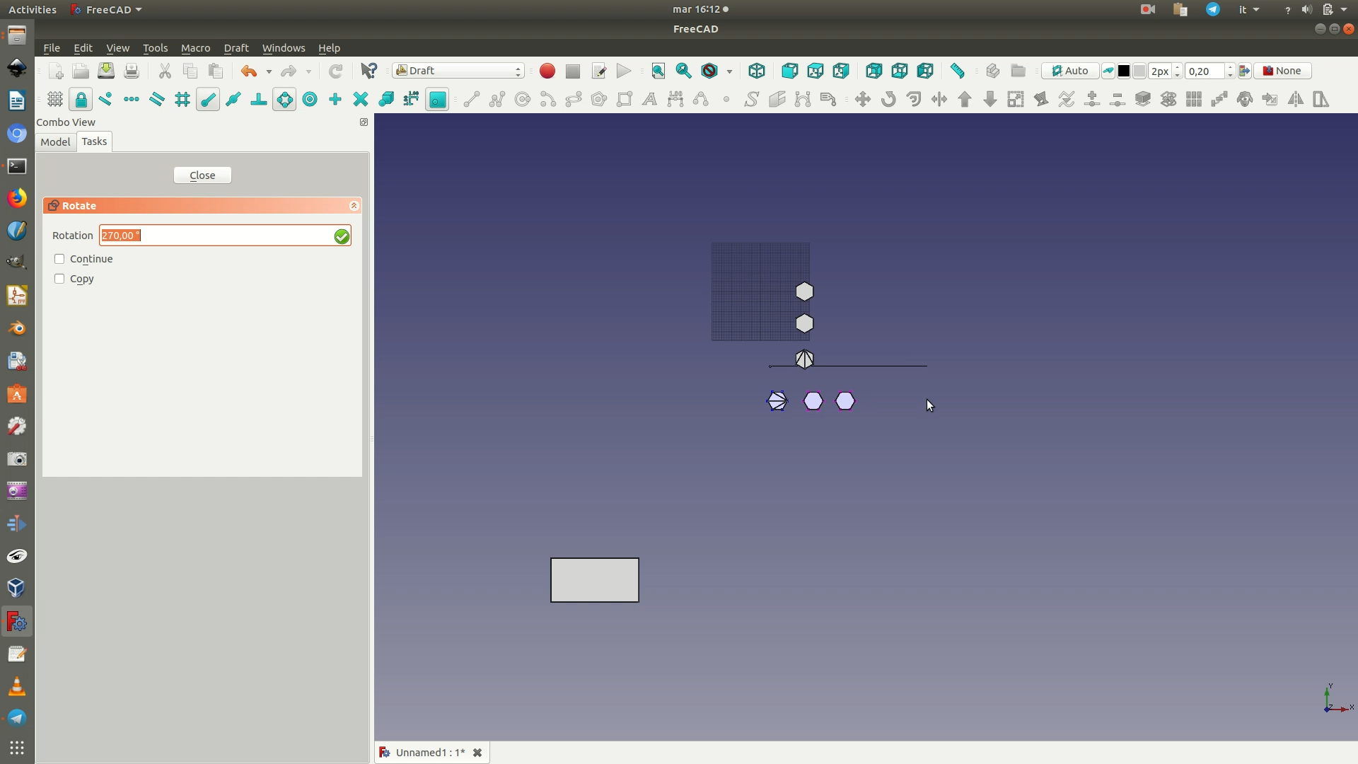
13. Switch to the Draft workbench. Navigate to the top view by going through View > Standard views > Top. Then rotate the objects by going through Draft > Rotate and align the three hexagons so that they are parallel to the rectangle you previously modeled. Now move the three hexagons closer to the rectangle by going through Draft > Move.
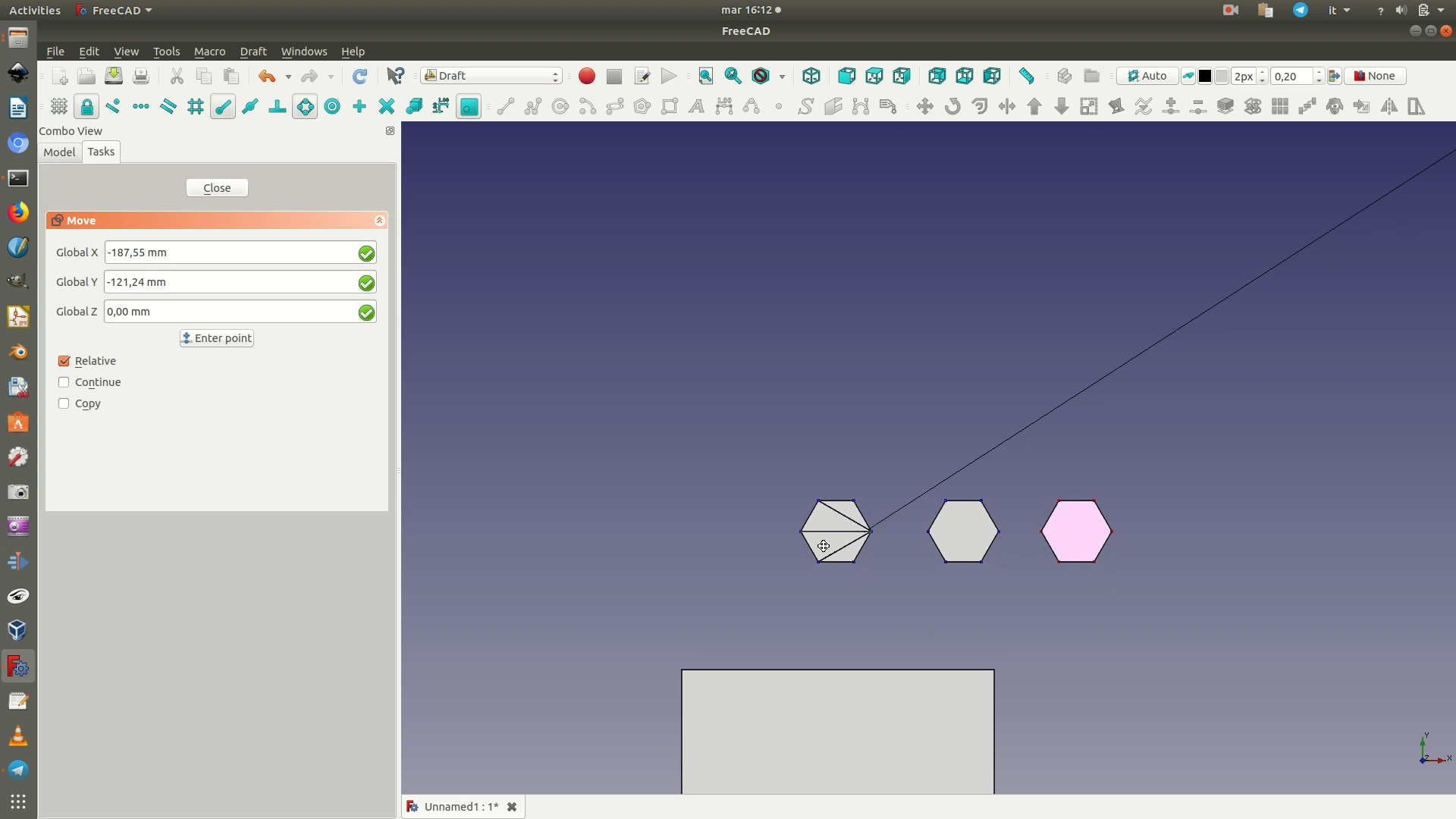
14. Go witch to the Part Design workbench. Select the last Body element from the left sidebar. Click on the top face of the rectangle and go through the menu Part Design > New Sketch. Inside the base rectangle, draw three segments like in the image below, by going through Sketch > Sketcher geometries > Create line. Make the three of them of equal length by selecting them all and applying the Equality Constraint (Sketch > Sketcher constraints > Constrain equal). Make each of these three lines of the same length as one of the edges of the hexagonal polygons, in this case 10,19mm. To do so, click on one of the three segments and apply a Horizontal Distance Constraint (Sketch > Sketcher constraints > Constrain horizontal distance). Type in 10,19mm as the length.
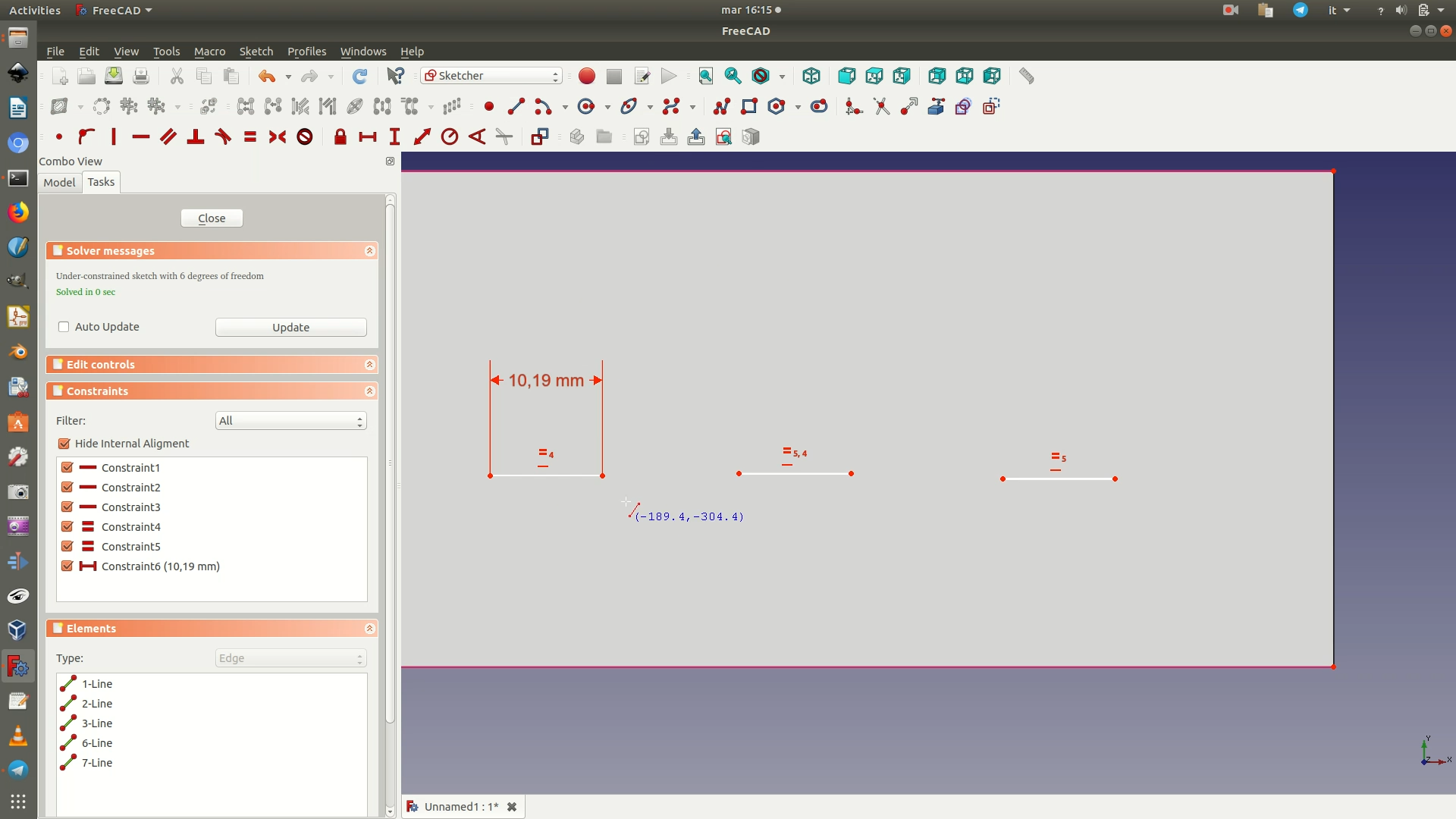
15. Toggle to Construction Mode. Construction mode allows you to draw lines that are not actually part of the object itself, but that only serve as modeling supports. To switch to Construction Mode, go through the menu Sketch > Sketcher Geometries > Toggle Construction GeometryConstruction Mode has been activated. Now navigate through Sketch > Sketcher geometries > Create line. Draw two lines connecting the three lines previously drawn, like in the image below. Select the two blue lines make them of equal length by applying the Equality Constraint (Sketch > Sketcher constraints > Constrain equal).
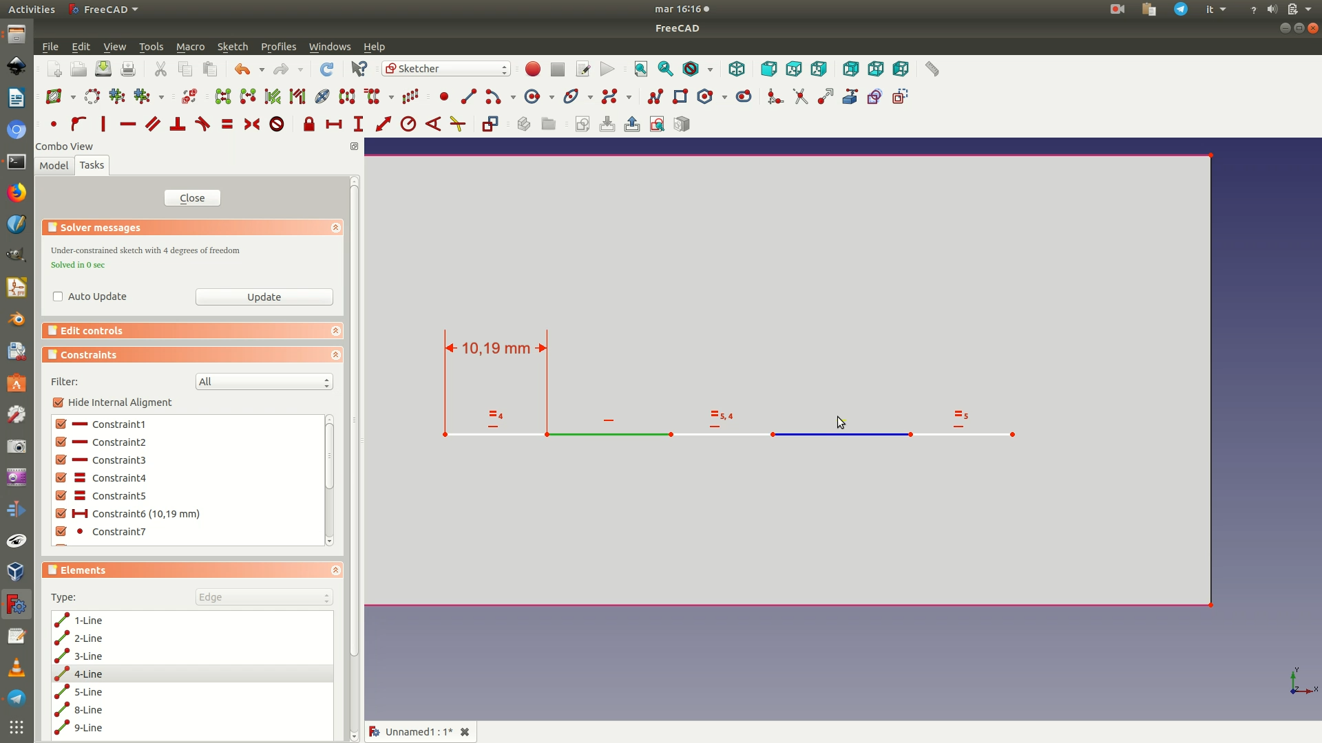
16. Without exiting Construction Mode, draw other lines to match those in the illustration below and apply the Equality Constraint (to the four diagonal lines); a Horizontal Distance Constraint of 60mm (between the extreme points of the long horizontal line made up of 5 segments); and a Vertical Distance Constraint of 17,64mm (to the two vertical lines). This will position the three white segments in the correct position. Close the sketch.
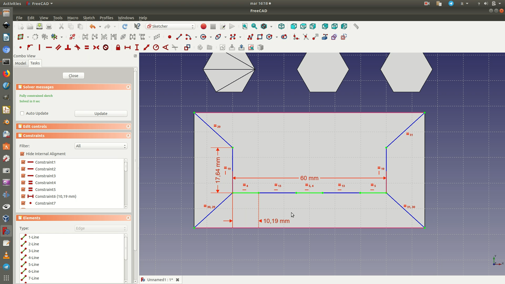
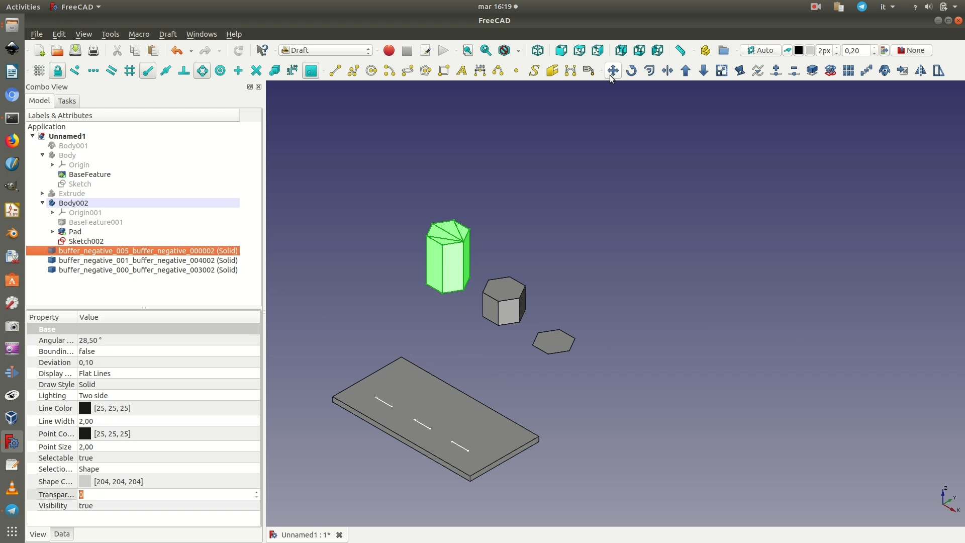
17. Switch to the Draft workbench. Select the highest hexagon polygon. Go through Draft > Move. In FreeCAD, you define movements by clicking the starting point and arrival point of the movement. In this case, first click on the bottom right corner of the base of the polygon (see first image below), then click on the right ending point of the first segment (see second image below). In practice, this will align the hexagonal polygon to the white line. Repeat for the other two hexagonal polygons. You can also check by navigating to the top view by going through View > Standard views > Top (see third image below).
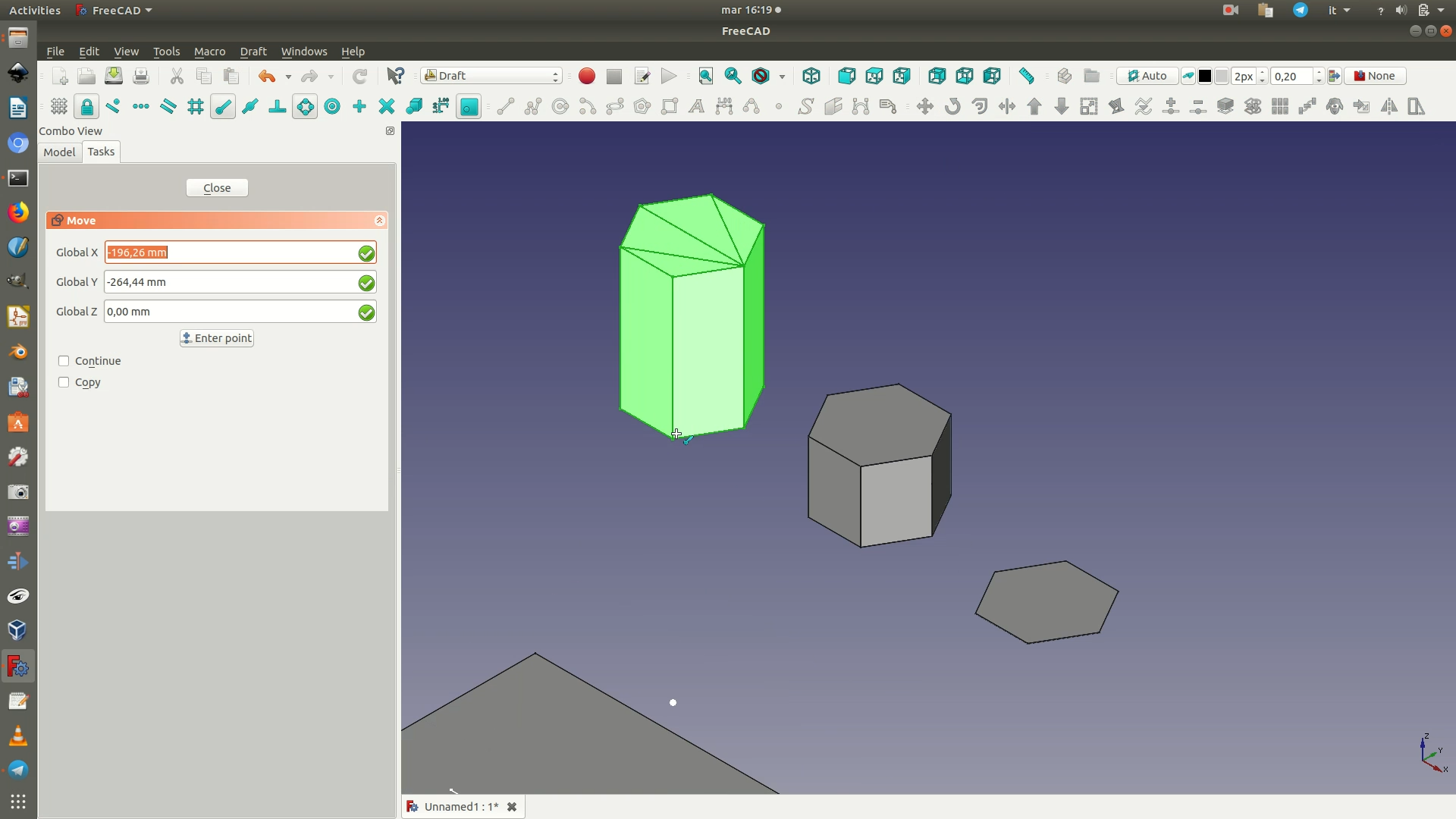
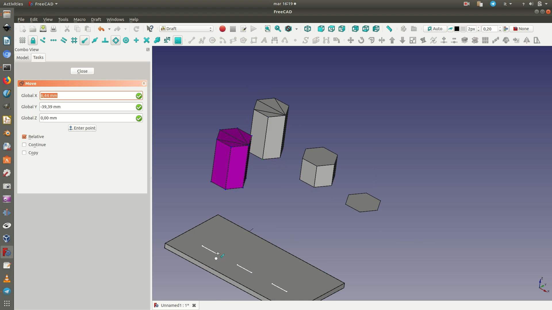
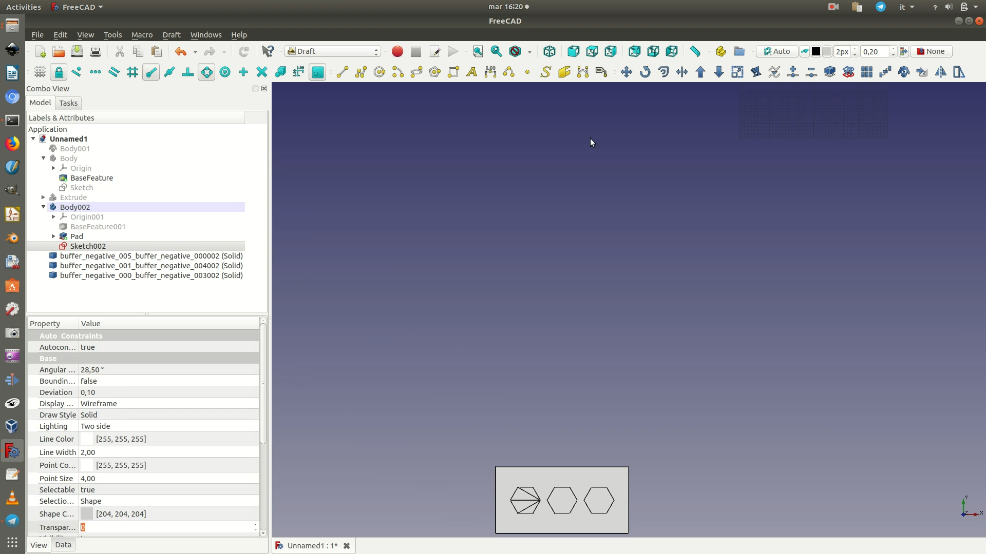
18. Navigate through Draft > Utilities > Select plane. Select the XZ plane. Select the three hexagonal polygons. Go through Draft > Move. Move them vertically until they snap on top of the base rectangle.
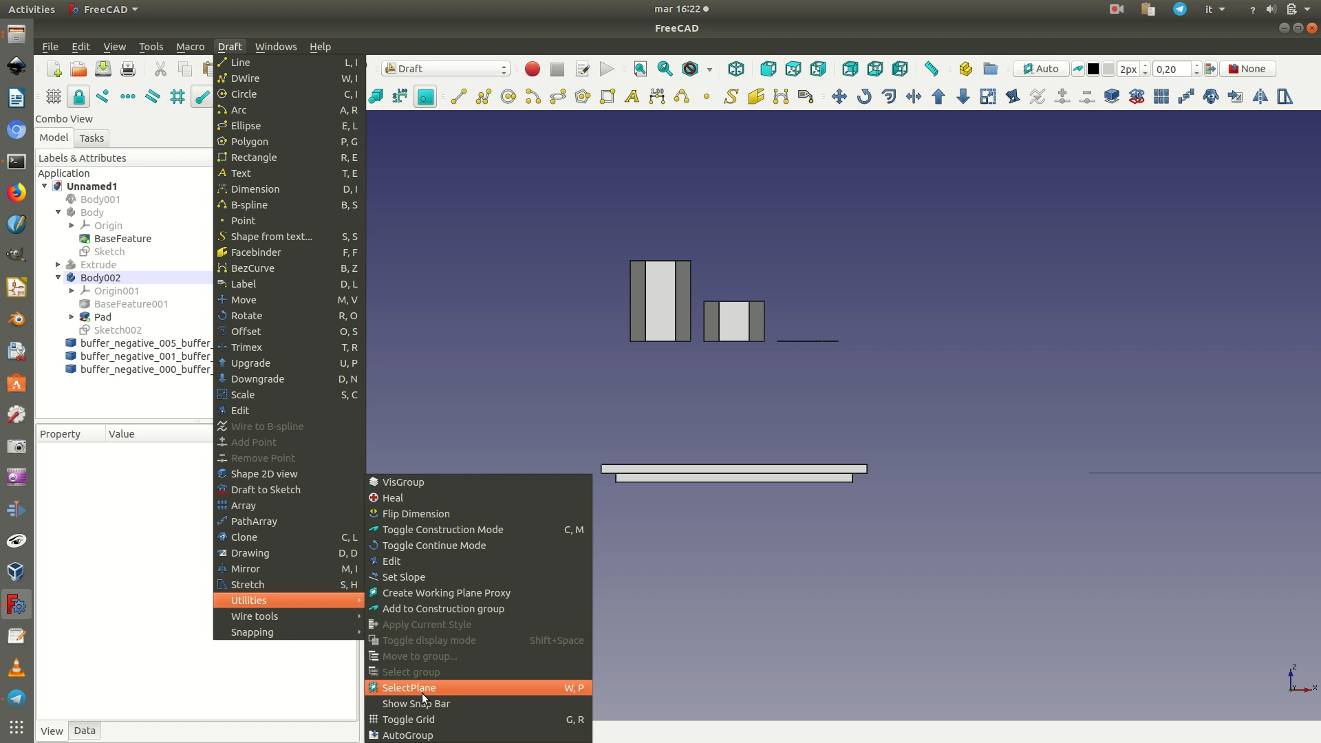
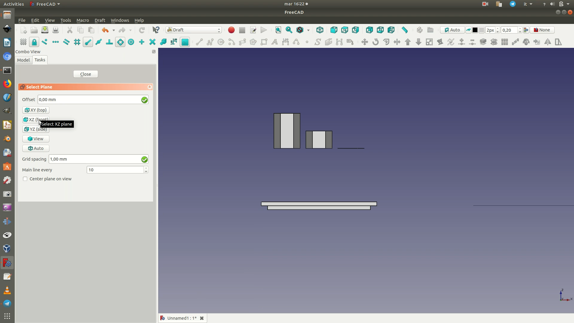
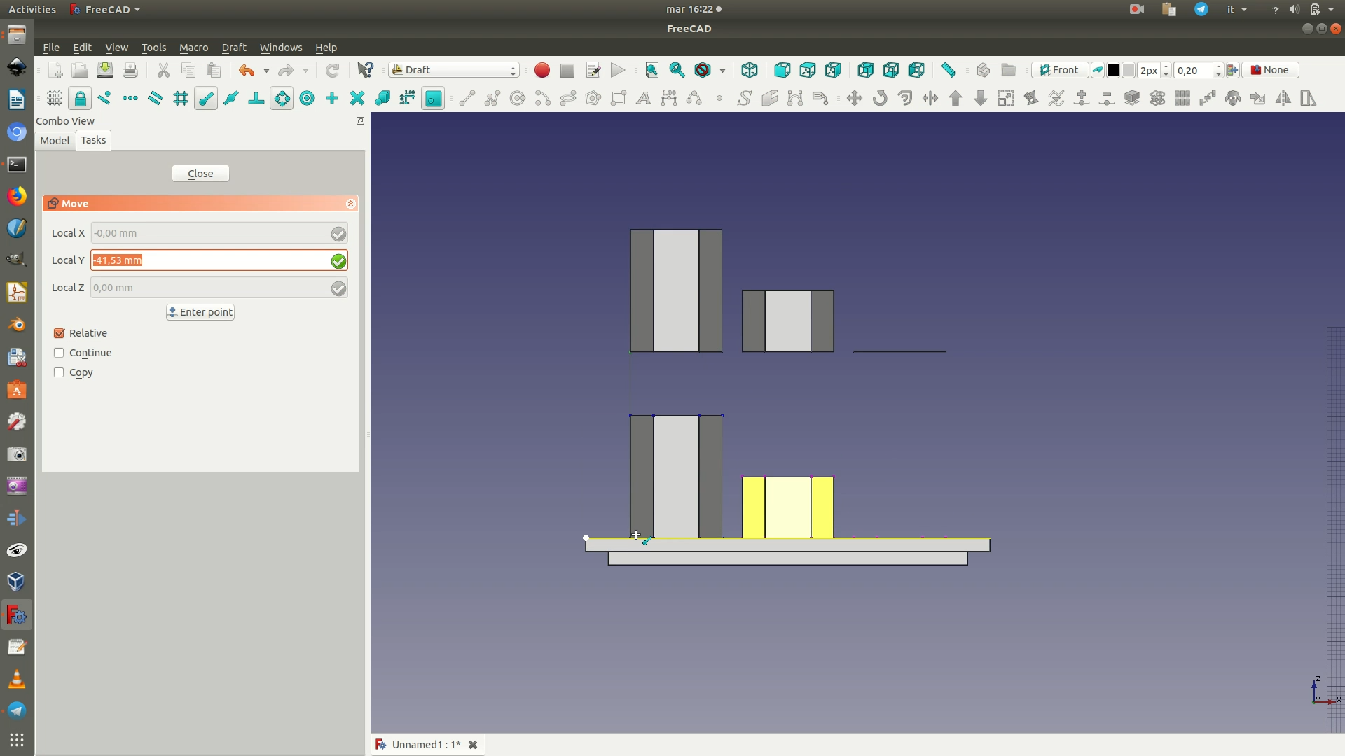
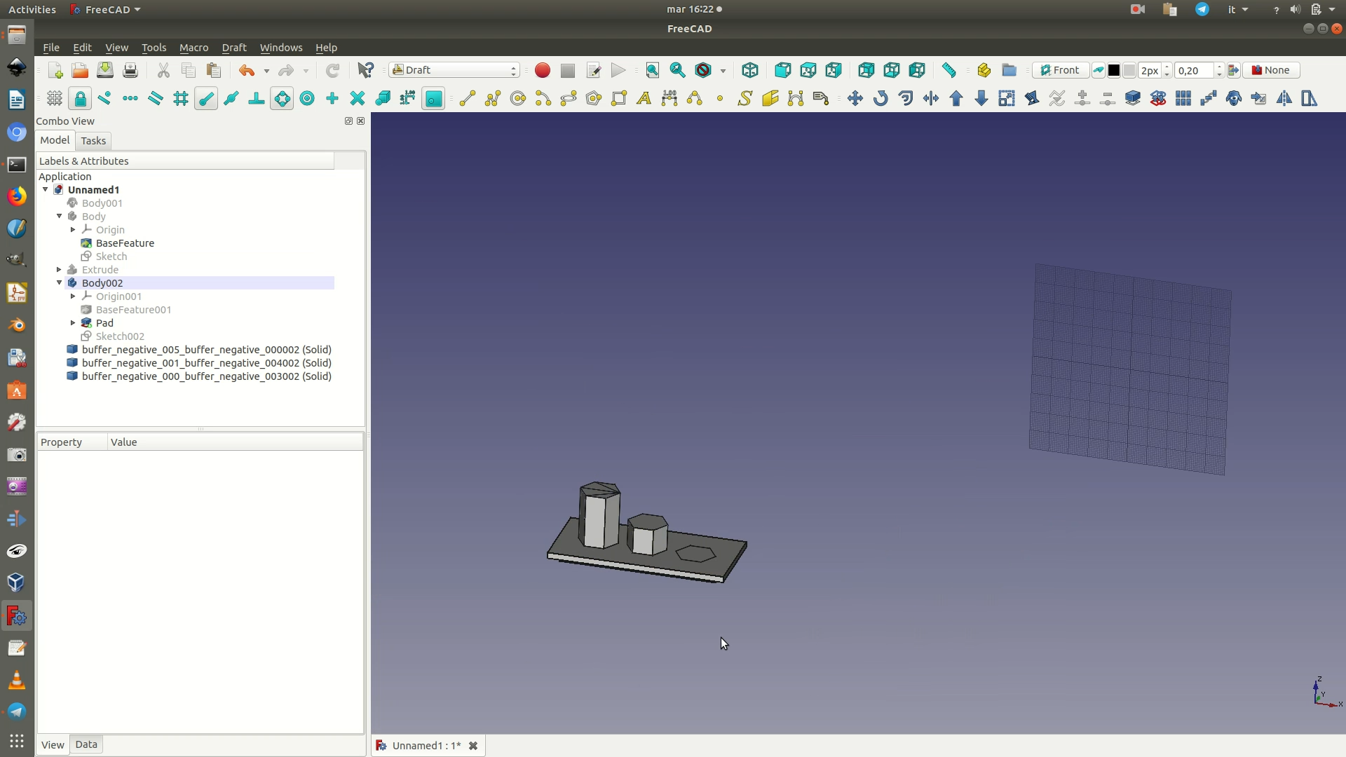
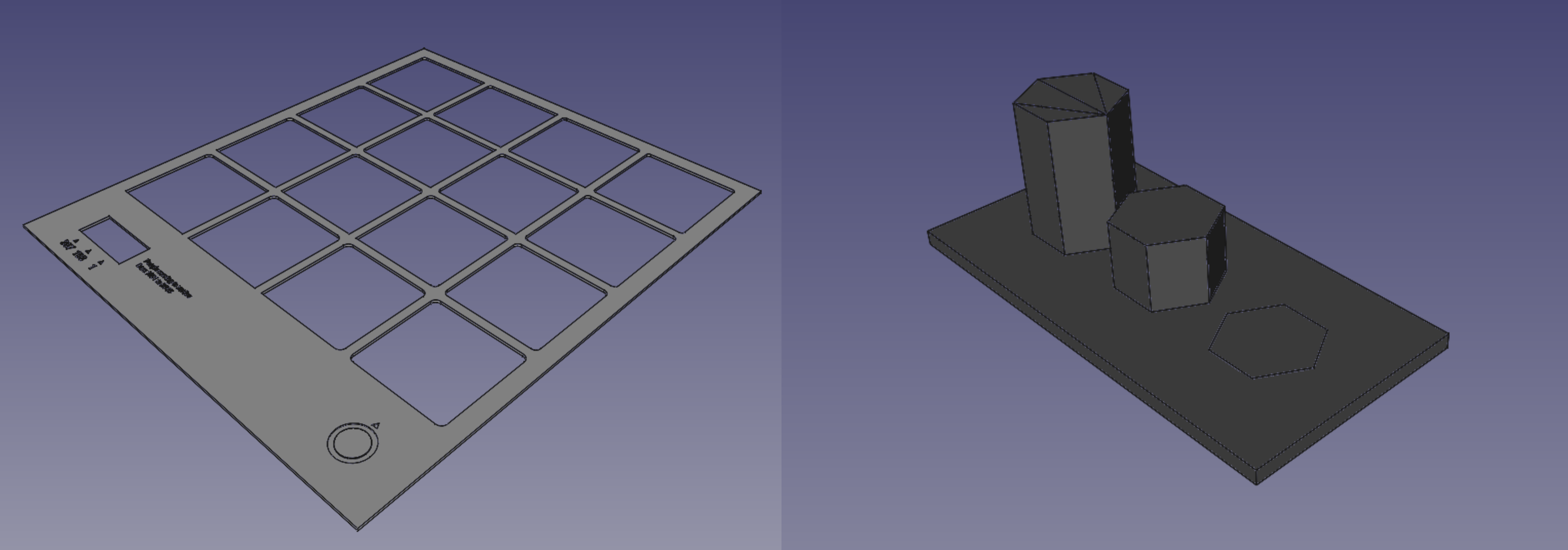
19. Switch to the Part workbench. Select the three hexagonal polygons and the base from the left sidebar. Navigate through Part > Boolean > Union. A new Fusion element, grouping all others, should now have appeared on the left sidebar.
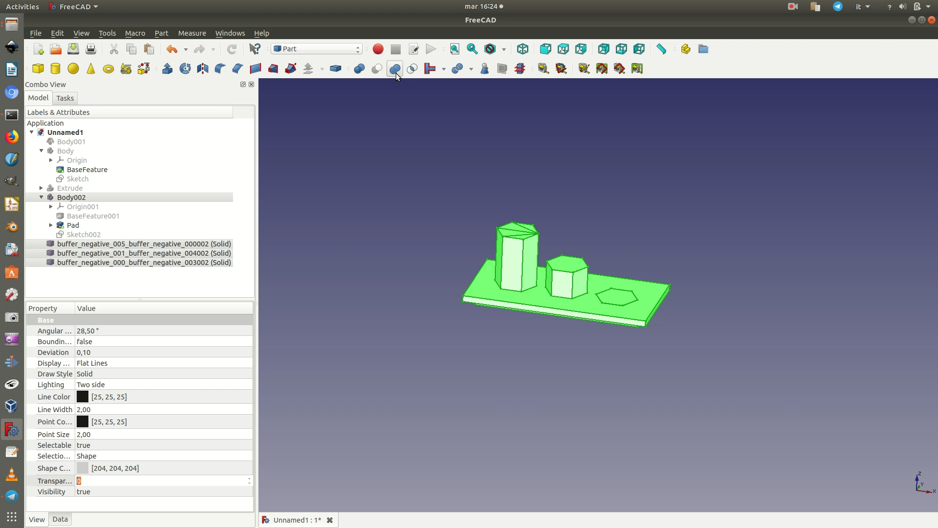
20. You can unhide the support grid you had hidden in step 9 to see the final result in context. Then, select the last Fusion element from the left sidebar, the one containing this last object created. Go through File > Export. Select .STL as the file type and export your project.
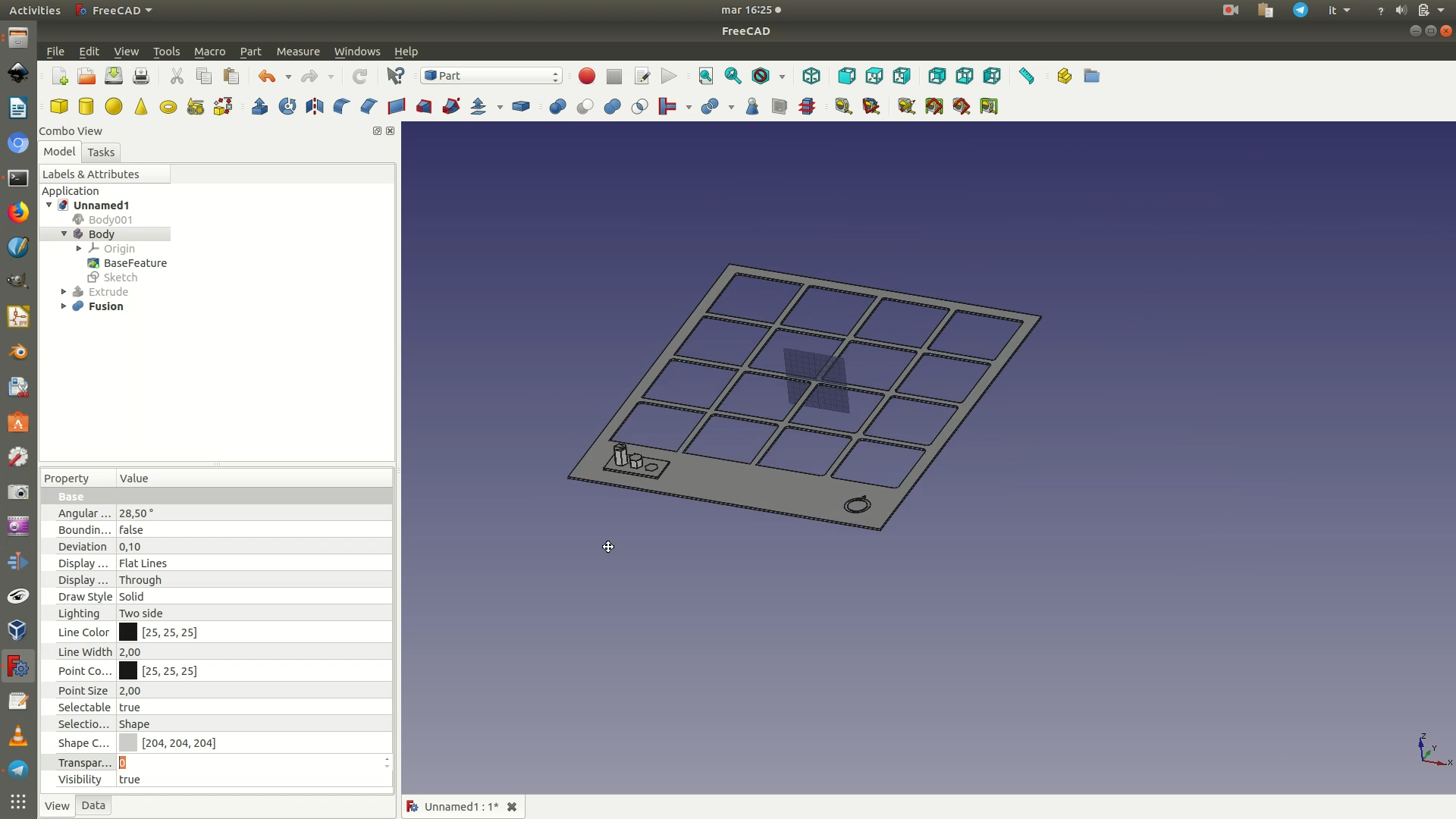
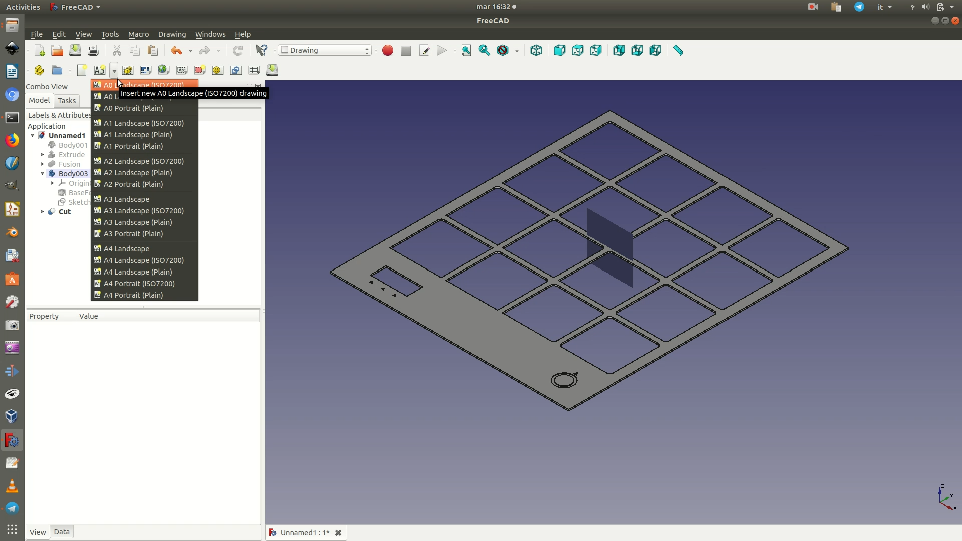
21. At last, you will add an engraving with the numbers that correspond to each hexagonal element of the legend. First, hide the last Fusion element so that you only see the data support grid, without the 3D legend. Move to the Drawing Workbench and click through the menu Drawing > Insert new drawing > A0 Landscape. A Page element will appear on the left sidebar and the window where your designed object was will radically change. It will now show a blank page (don’t panic).
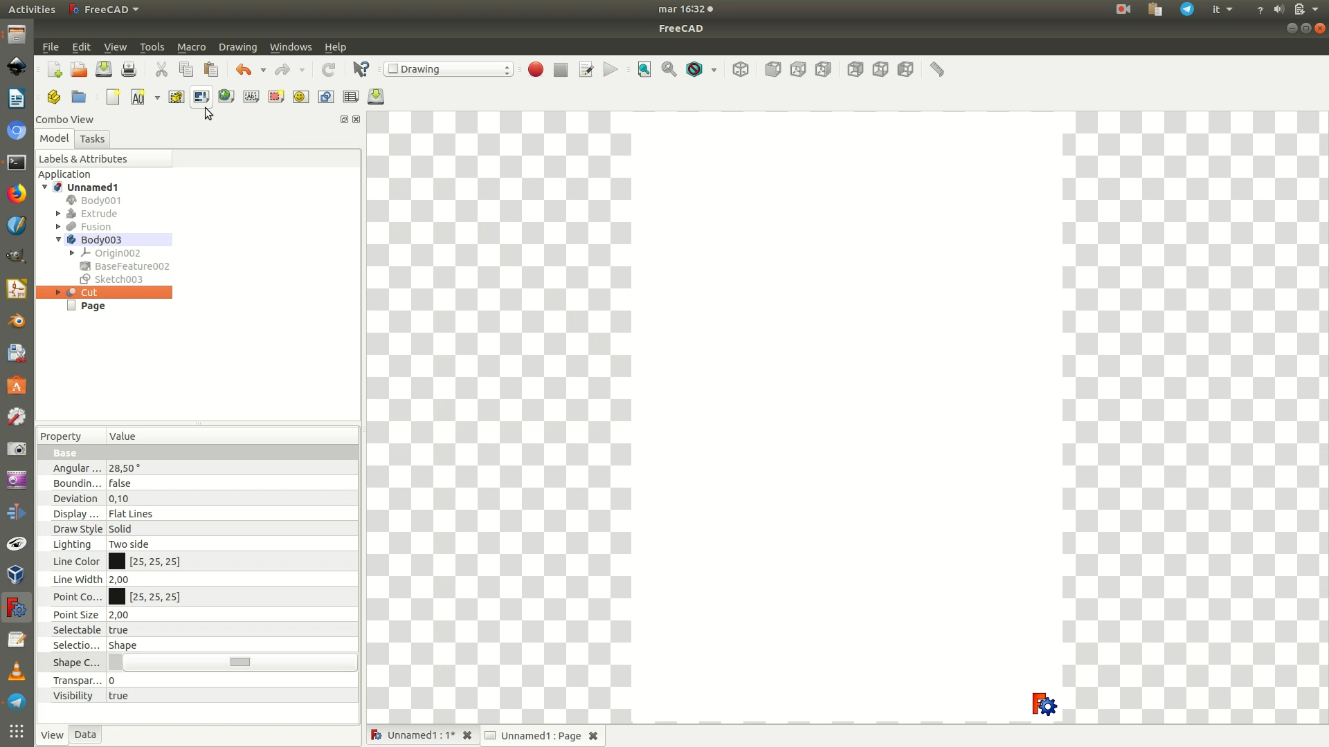
22. From the left sidebar, select the last Body element, the one corresponding to data support grid. Click through the menu Drawing > Insert Orthographic Views. A new interface with some options and checkboxes will appear on the left sidebar. Change the defaults so that the options and values match those in the image below. Then click OK.
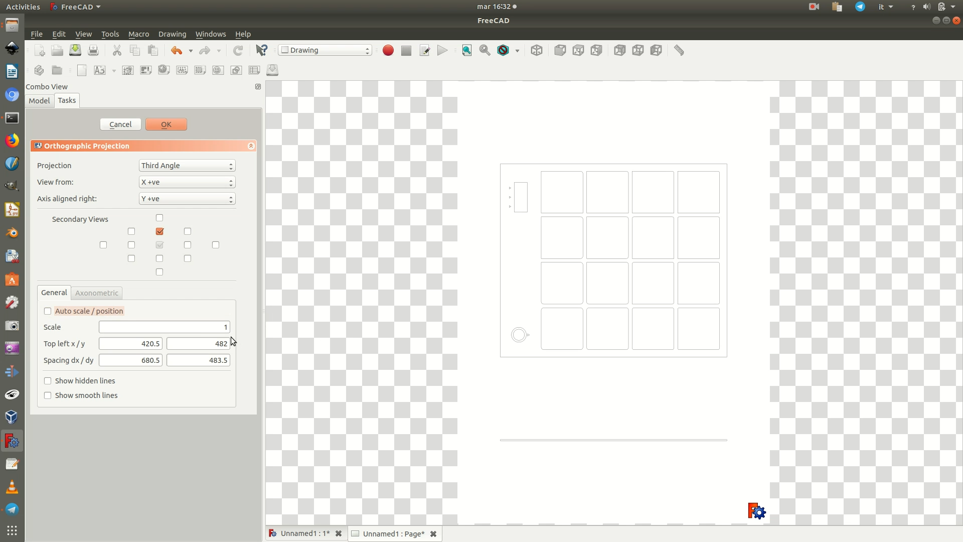
23. Click the Page element on the left sidebar, then go through the menu Drawing > Export page. Name the file and select a destination path. This will save the page as an .SVG graphics file.
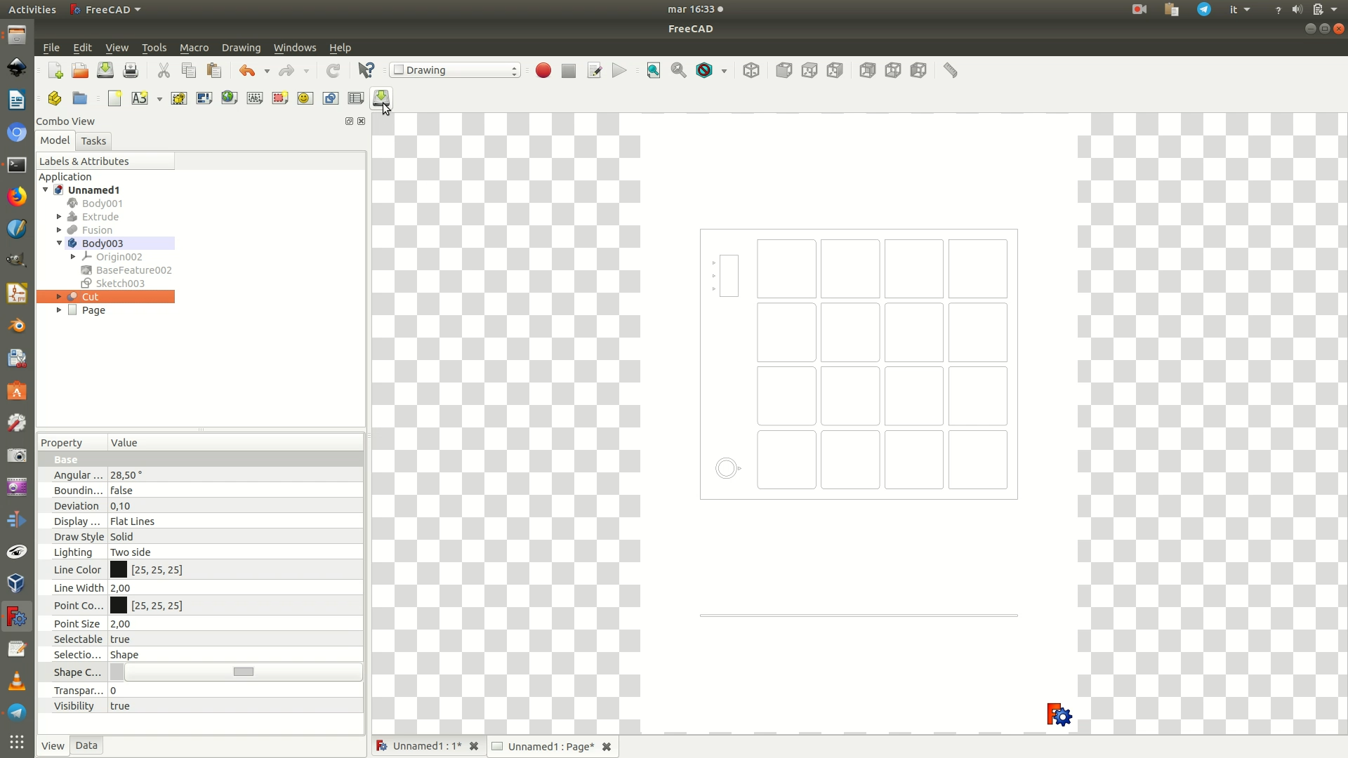
24. Open the .SVG file with a vector graphics software and add all the graphical elements you desire. Because this part is not strictly about 3D digital fabrication, but rather about 2D vector graphics, and because it can be done with any vector graphics software you might already be familiar with, we will skip the step-by-step text tutorial. You can watch the video (minutes 17:30 - 23:29) to see how we proceeded to create the graphics using Inkscape. Or you can also download the resulting .SVG graphics file from Github and edit/reuse it directly. If you are making your own .SVG graphics, make sure you convert all objects and texts to paths before proceeding to the export.
If you or your lab has a laser cutting machine, you can already use this .SVG file to engrave the base of the installation with these graphics. This will definitely save you time.
Otherwise, if you only have access to a CNC milling machine, you need to follow through with the next steps of tutorial.
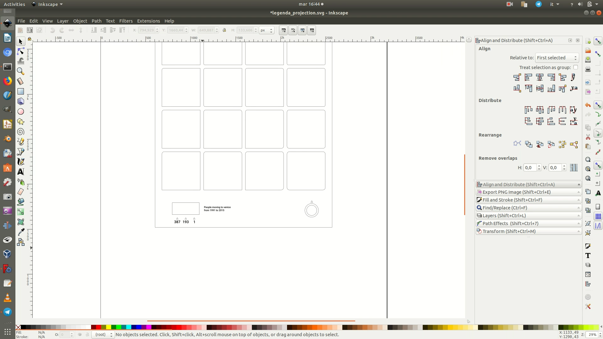
25. Once you have the graphics in place, you switch back to the FreeCAD project and import the .SVG file by going through File > Import. In the pop-up that appears next, make sure you select the option SVG as geometry (importSVG).
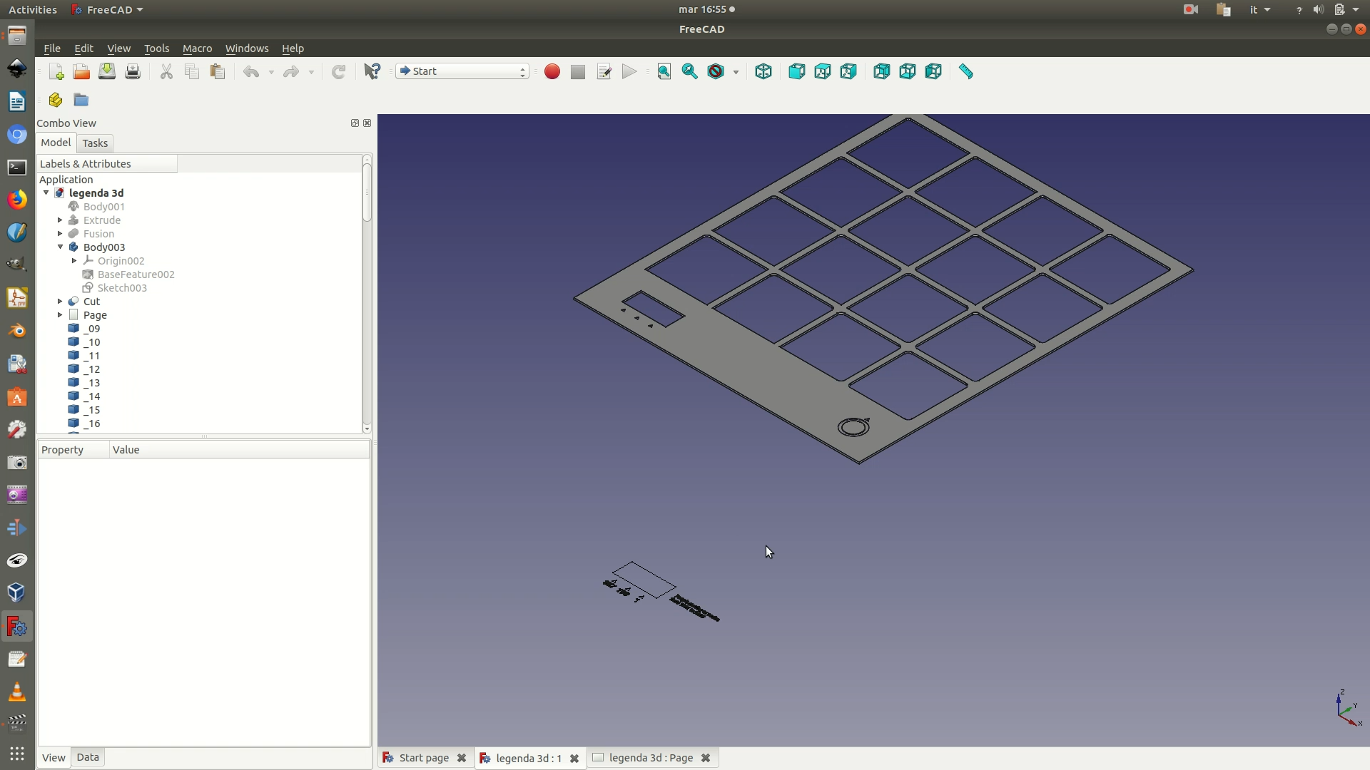
26. Switch to the Draft Workbench and select the top view by going through View > Standard Views > Top. Select all the elements that are part of the imported .SVG by selecting all of them on the left sidebar pane (see image below). Move them by clicking through the menu Draft > Move. On the panel that has appeared on the left, make sure you deselect the Copy option. You will then define the movement of all the selected elements by choosing (clicking) the starting point and ending point of the movement. The ending point should result in the graphics being aligned with the hole where the 3D legend will fit into.
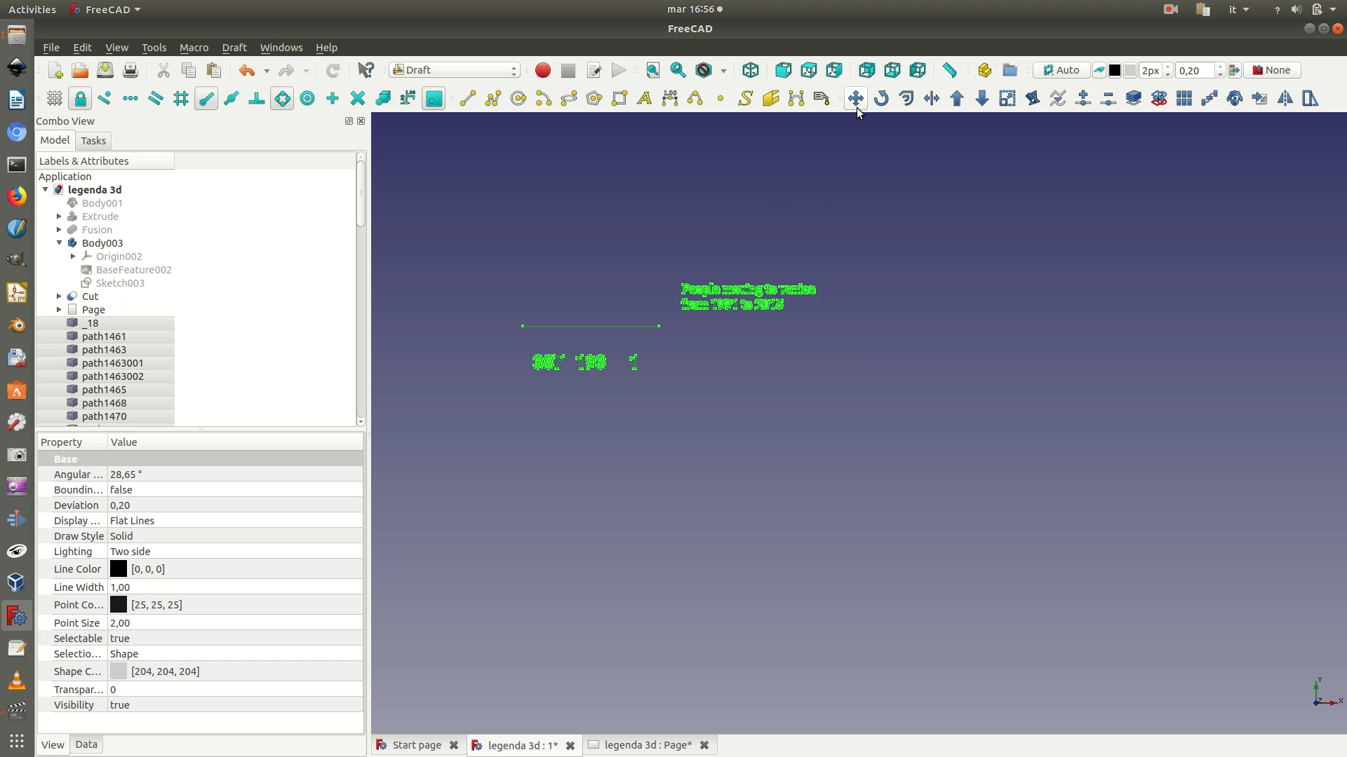
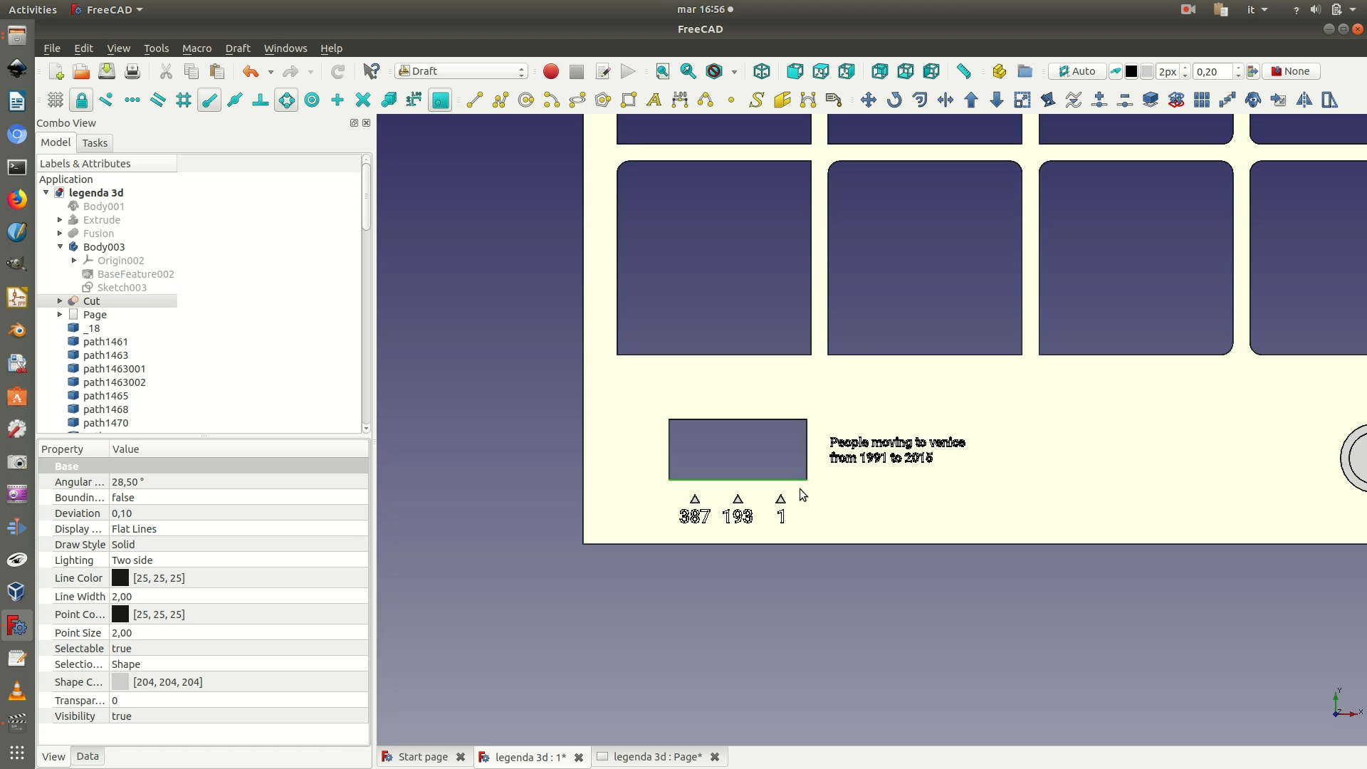
27. Once you are satisfied with the position of the vectors, switch to the Part Workbench and select the axonometric view by going through View > Standard Views > Axonometric. Hide the data support grid by selecting it from the left sidebar and right clicking through Hide Selection (or hit the spacebar).
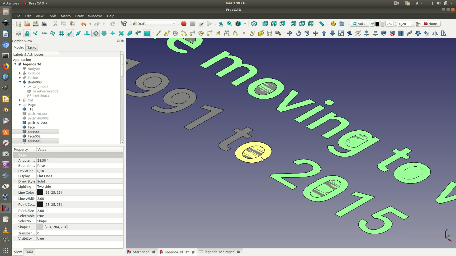
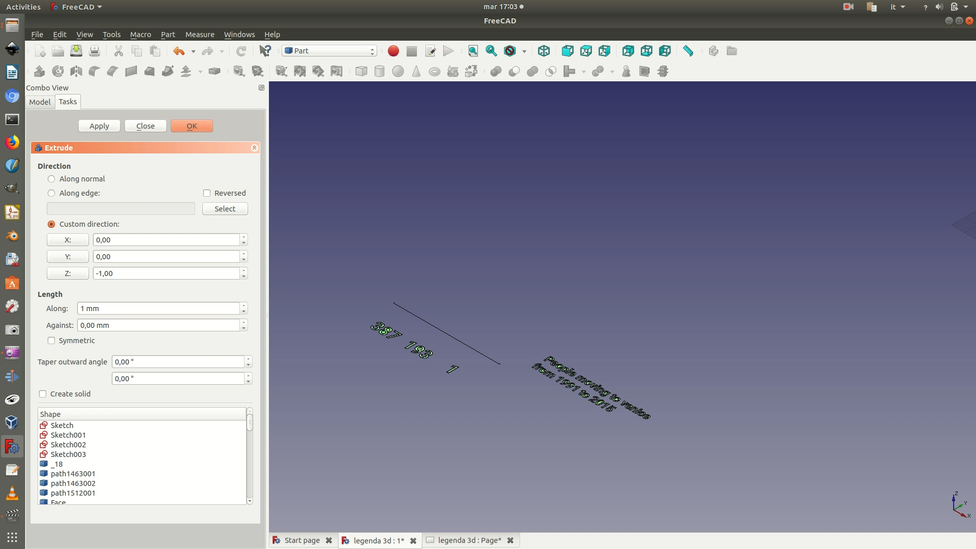
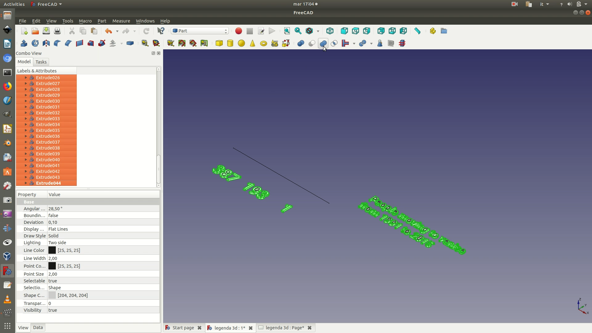
With your mouse cursor, from the 3D layout, select all the outlines of the letters and numbers that are part of your graphic. Make sure you also don’t select the “holes” (technically: the counters) of the letters and numbers. With all of them selected, click on the menu Part > Extrude. In the selection panel that has appeared on the left, set the following parameters:
Custom direction > Z: -1Length > Along > 1 mm(this is how deep the text will be engraved on the material you are engraving it upon)
Click OK. Depending on your machines, it might take a few seconds, but at the end of the processing you will see a 3D model of the vectors and several new Extrude elements on the left sidebar.
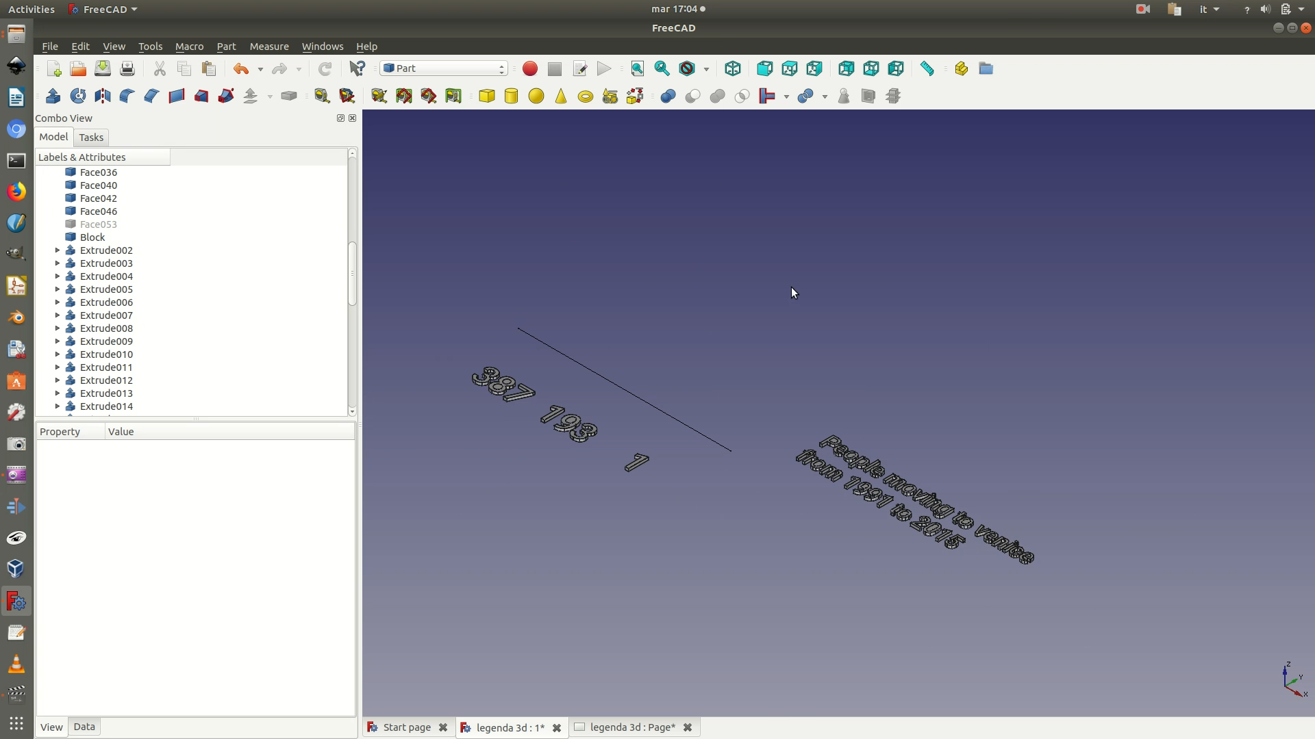
28. Unite all the Extrude elements that make up your graphics in a single element. To do so, select all the Extrude elements on the left sidebar and then go through the menu Part > Boolean > Union. This process might also take a bit of time to complete, depending on your CPU. When it’s done, you will see that, on the left sidebar, a Fusion element has replaced all the single Extrude elements.
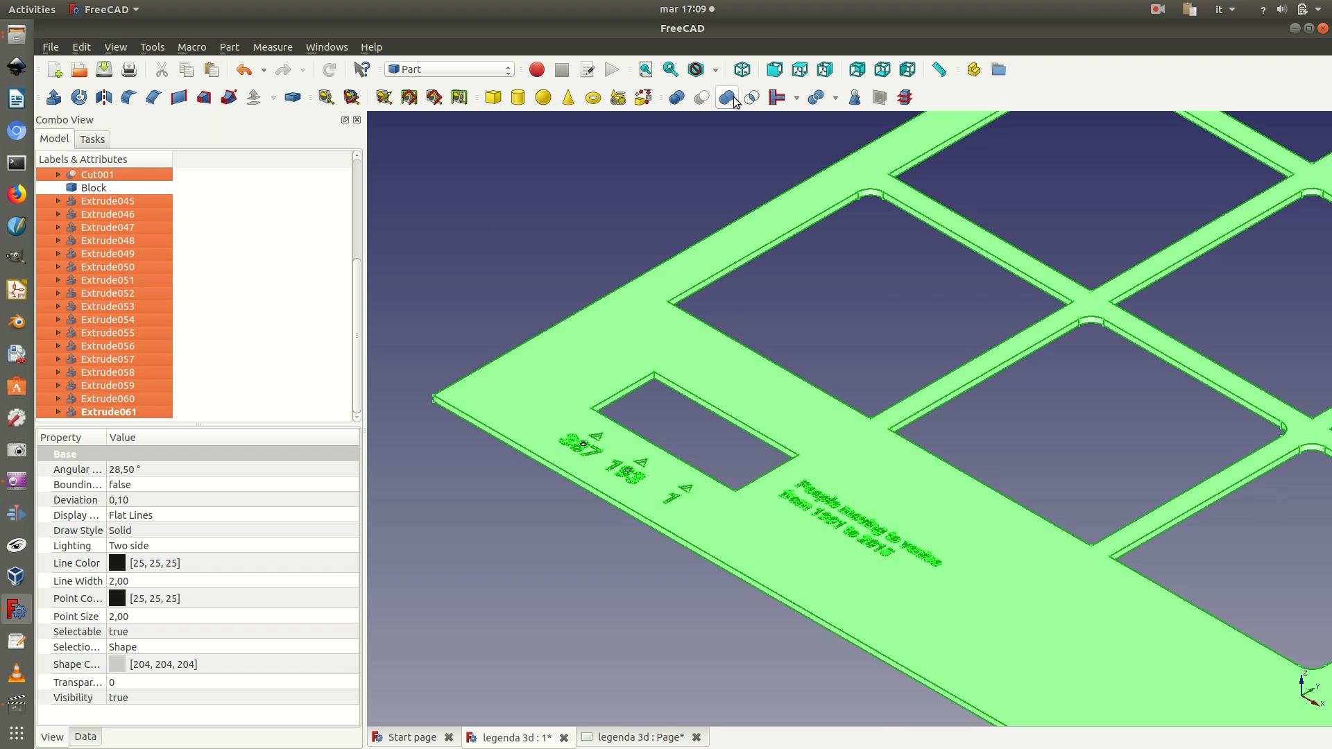
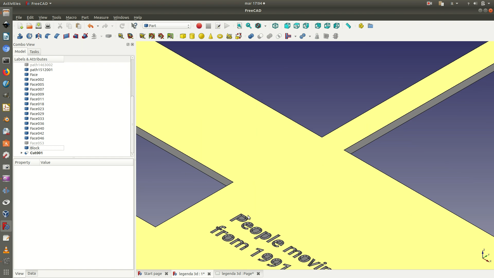
29. Unhide the data support grid by selecting the corresponding Body element on the left sidebar and right-clicking through Show selection. Now select both this Body element and the Fusion element from the left sidebar, making sure that the Body element is the first one you select. Go through Part > Boolean > Cut. Again, depending on your CPU, this process might take a few seconds. At the end of the operation, if you look at the left sidebar, you will notice that both the Body element (the support grid) and the Fusion element (the graphics) have been grouped under a new Cut element.
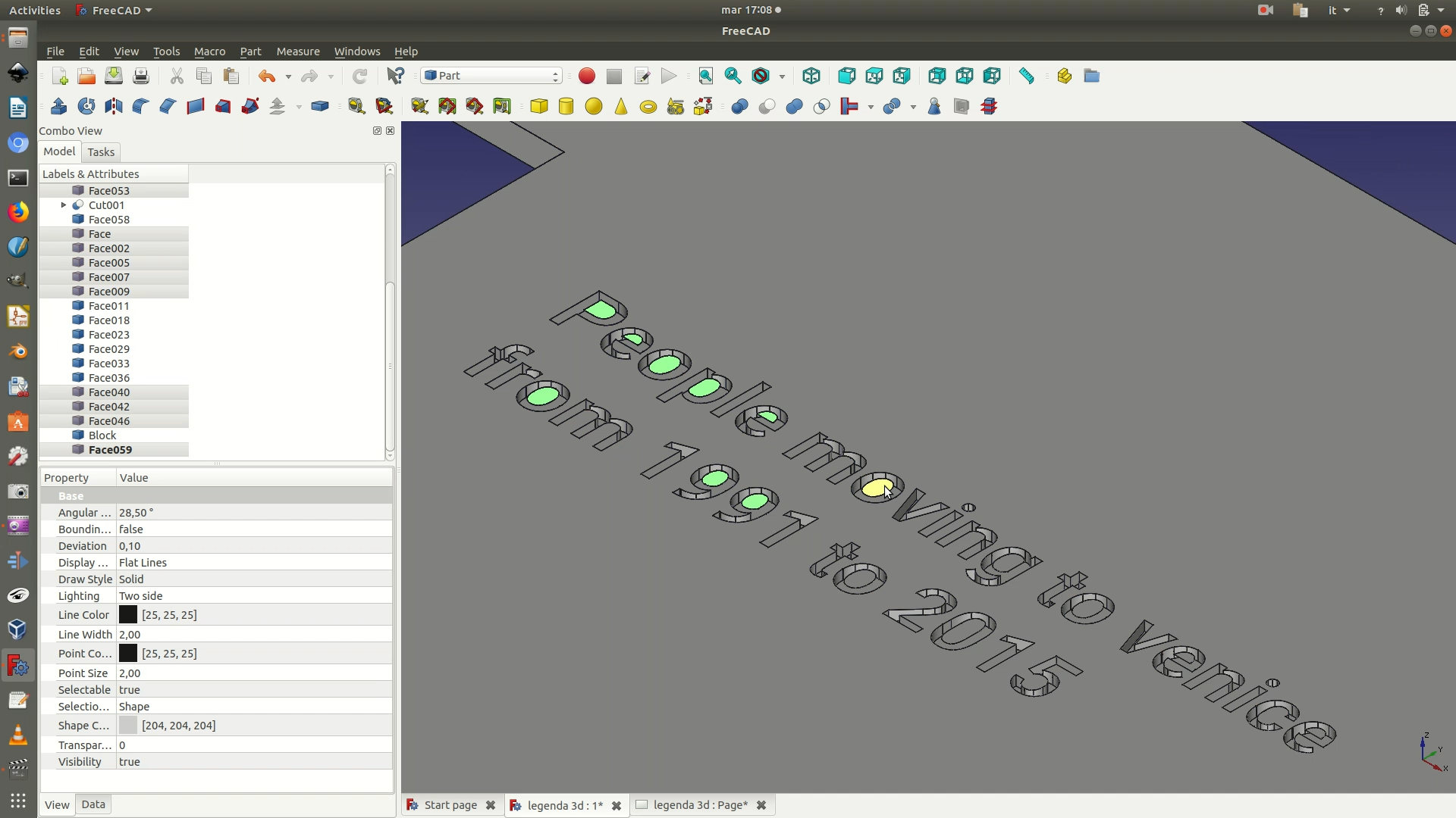
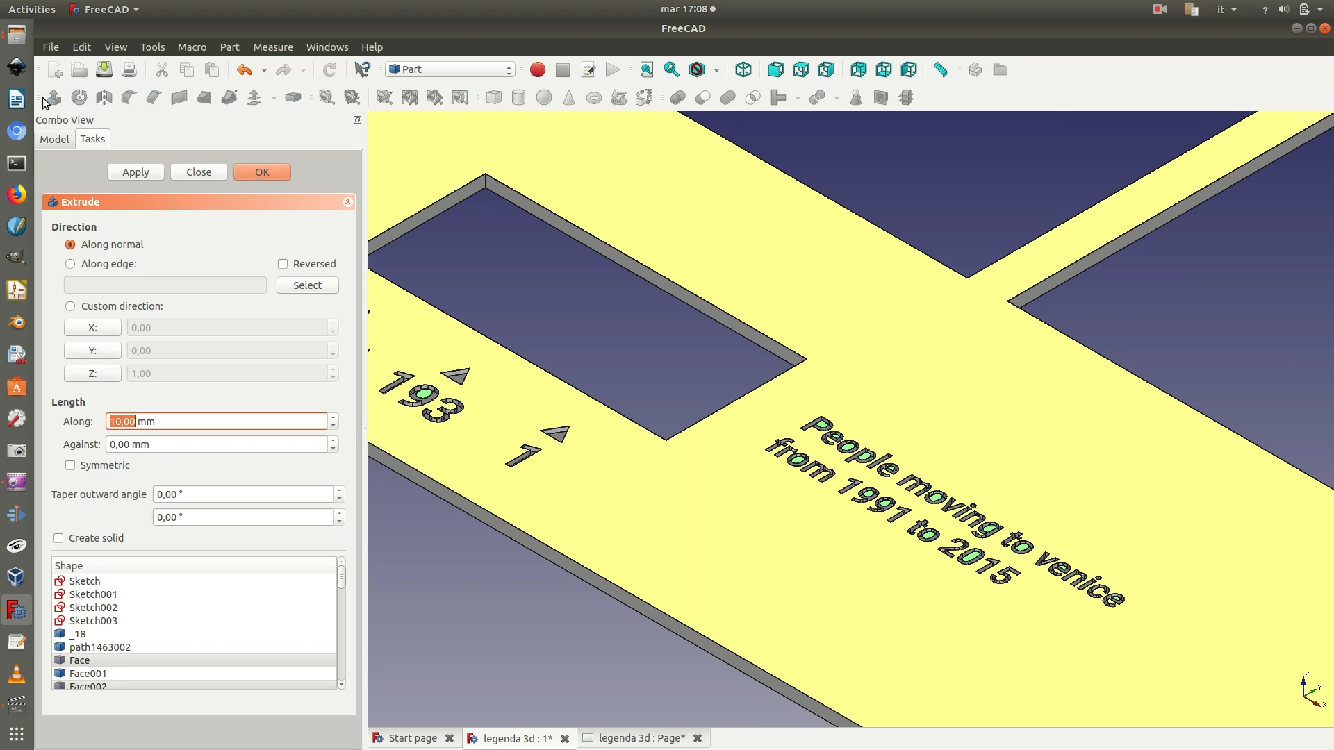
30. As you can see, because of how extrusion works, it didn’t handle all the letters and numbers as desired. This is due to the fact that the command has no way of detecting the difference between a line and what we perceive as a “hole”/counter. To remedy this, first select all the outlines of the counters in your text. With all of them selected, click on the menu Part > Extrude. In the selection panel that has appeared on the left, set the following parameters:
Custom direction > Z: -2Length > Along > 2 mm(so that they are engraved deeper than the letters, which had a value of 1, but are not cut all the way through the material, which has a thickness of 3mm)
Click OK . Depending on your machines, it might take a few seconds, but at the end of the processing you will see a 3D model of the vectors and several new Extrude elements on the left sidebar.
31. As a last step, you need to unite all the extruded number/letter counters (the last Extrude elements) with the data support grid with the graphics engraved (the last Cut element). To do so, select both this Cut element and the Extrude element from the left sidebar, making sure that the Cut element is the first one you select. Go through Part > Boolean > Union. Again, depending on your CPU, this process might take a few seconds. At the end of the operation, if you look at the left sidebar, you will notice that both the Cut element (the engraved support grid) and the Extrude element (number/letter counters) have been grouped under a new Fusion element. Your file is now ready to go into fabrication, so make sure you save it and export it as .STL
