3D Modeling · Data Walk
Part 3 - Text & graphics
Full Video Tutorial
Workflow explanations
Download final 3D modeling files
1. Hide the two Array elements so that again only the base is showing. Move to the Drawing Workbench and click through the menu Drawing > Insert new drawing > A0 Landscape. A Page element will appear on the left sidebar and the window where you designed object was will radically change. It will now show a blank page (don’t panic).


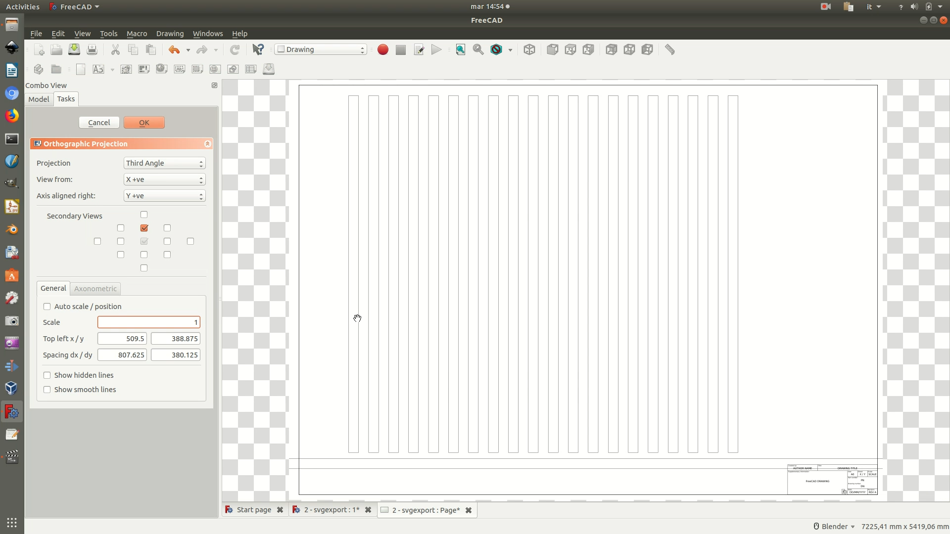
2. Select the last Cut element from the left sidebar. Click through the menu Drawing > Insert Orthographic Views. A new interface with some options and checkboxes will appear on the left sidebar. Change the defaults so that the options and values match those in the image below. Then click OK.

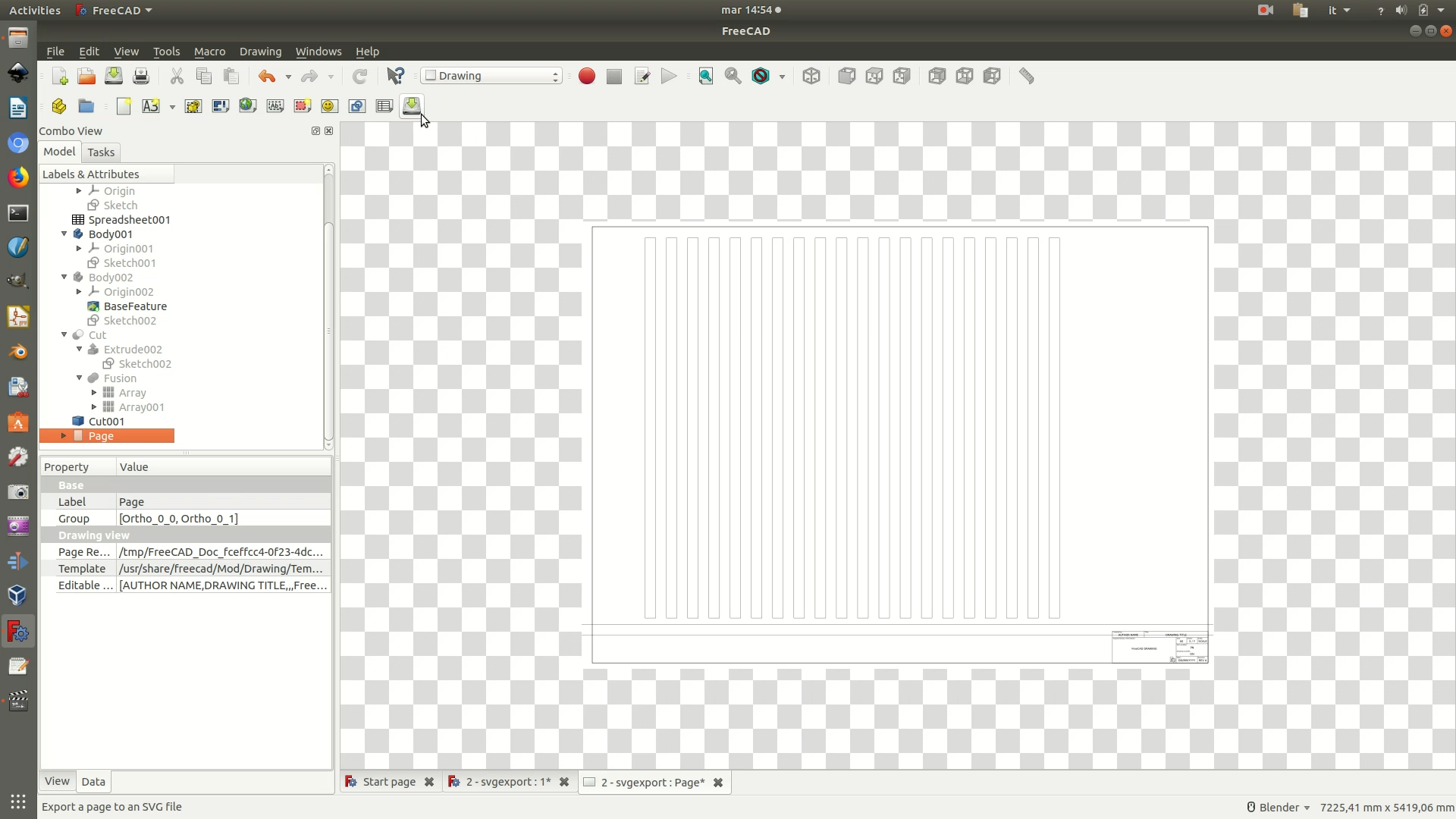
3. Now it’s time to export the project. Click the Page element on the left sidebar, then go through the menu Drawing > Export page. Name the file and select a destination path. This will save the page as an .SVG graphic file.
4. Open the file with Inkscape. Click on one of the four edges of the base and move it aside, so that you can then easily select everything except the base and delete it. See the second image below for the results of this operation.
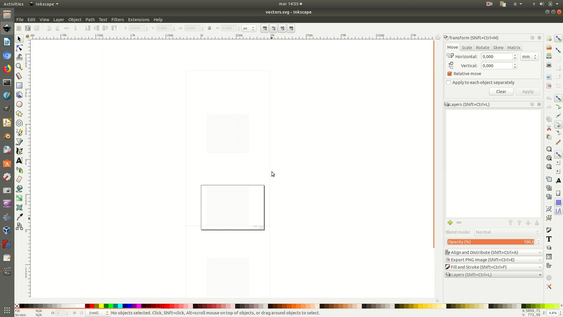
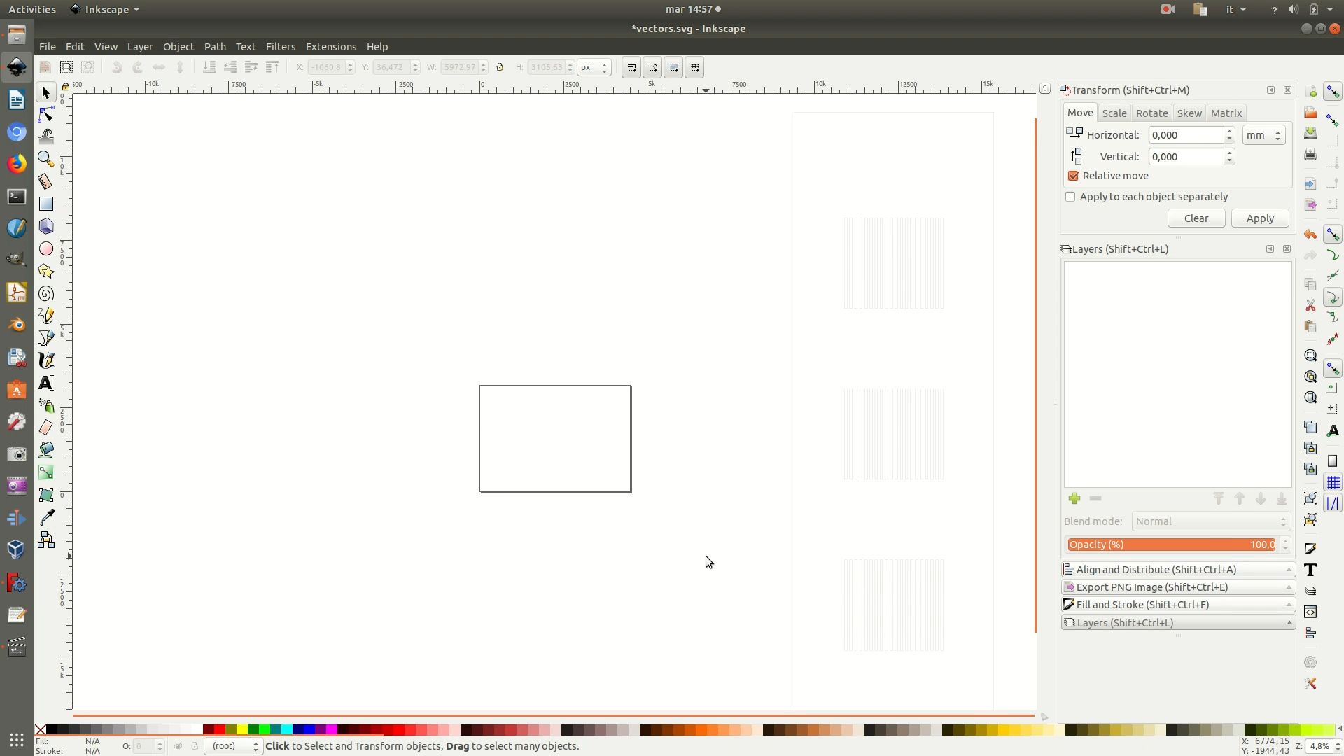
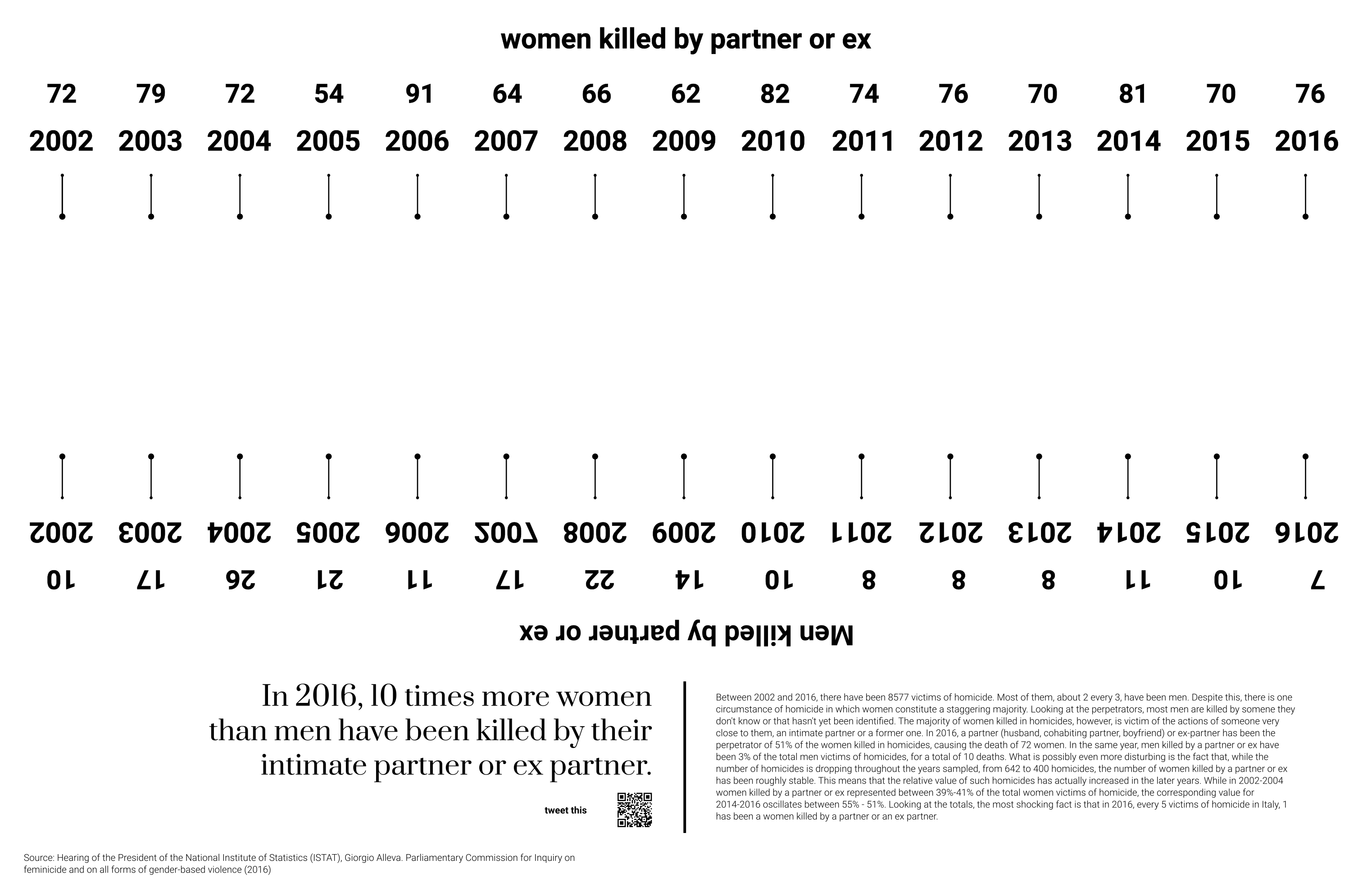
5. At this point, you can open the .SVG file with a vector graphics software and add all the graphical elements you desire. Because this part is not strictly about 3D digital fabrication, but rather about 2D vector graphics, and it can be done with any vector graphics software you might already be familiar with, we will skip the step-by-step text tutorial. If you want to receive guidance, you can watch the video uploaded at the top of the page, which includes how we created the graphics using Inkscape. Or you can also download the resulting .SVG graphics file from Github and edit/reuse it directly, without starting from scratch, and then proceed with the following steps. If you are making your own .SVG graphics, make sure you convert all objects and texts to paths before proceeding to the export.
Note that if you or your lab has a laser cutting machine, you can already use this .SVG file to engrave the base of the installation with these graphics, without following through with the rest of this section. This will definitely save you time.
Otherwise, if you only have access to a CNC milling machine, you need to follow through with the next steps of tutorial.
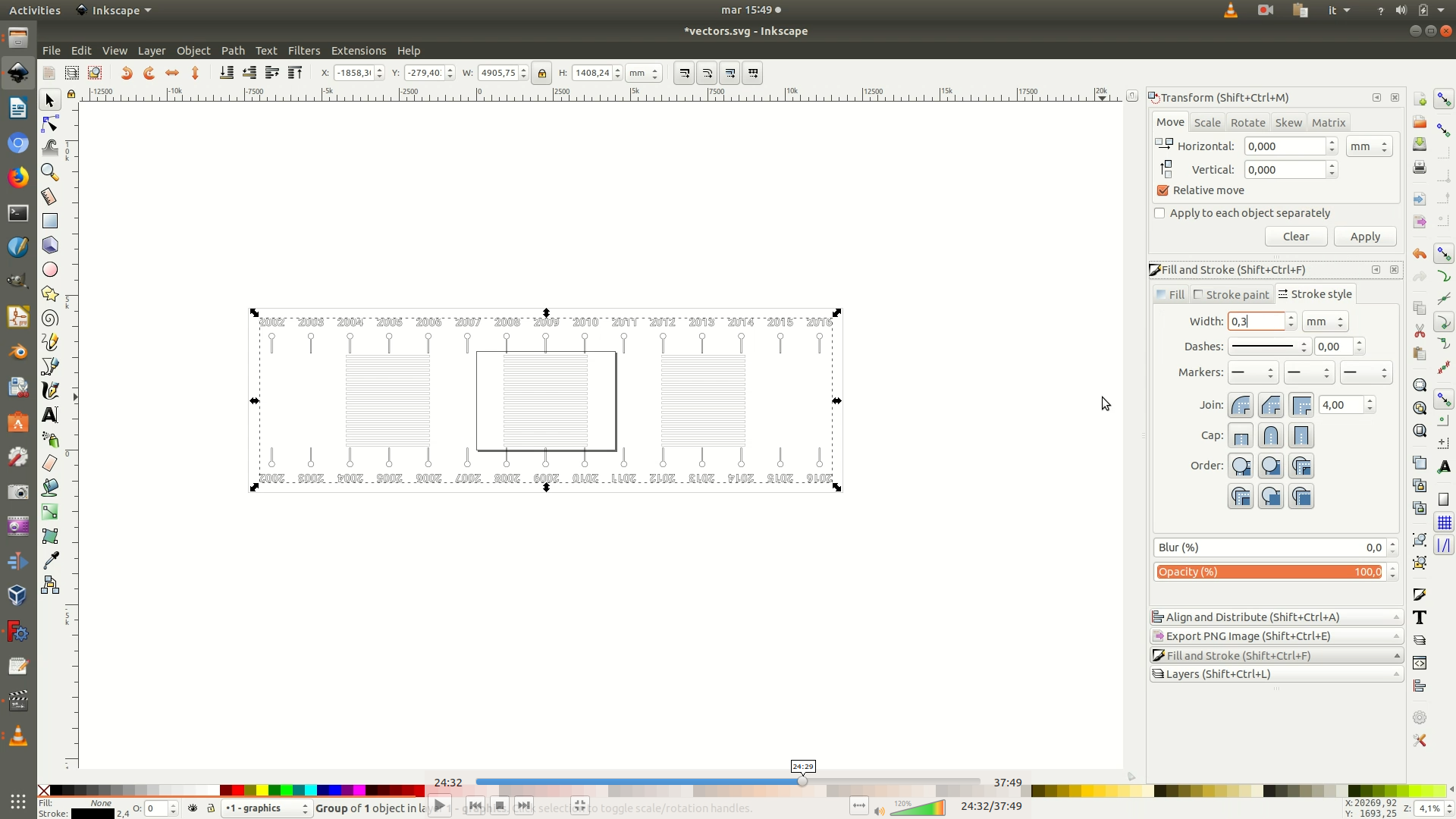
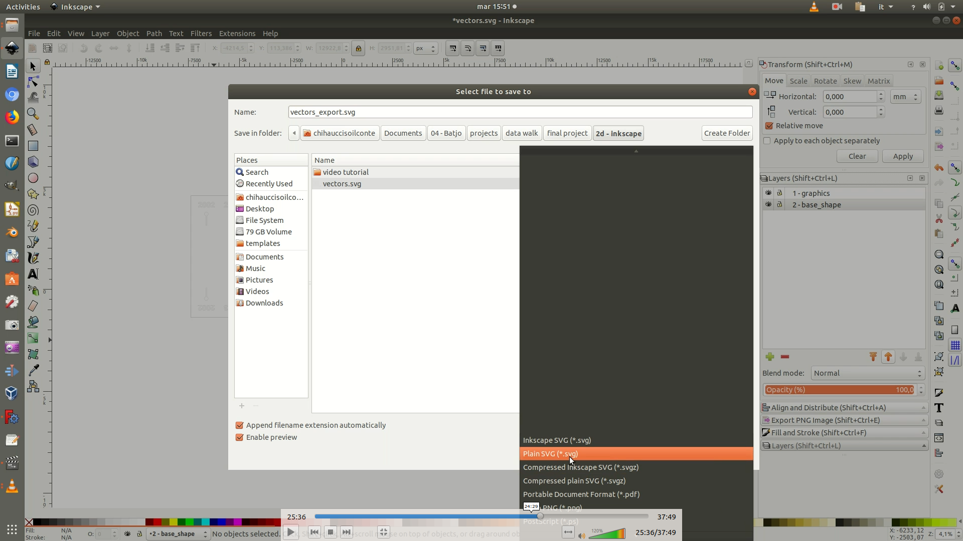
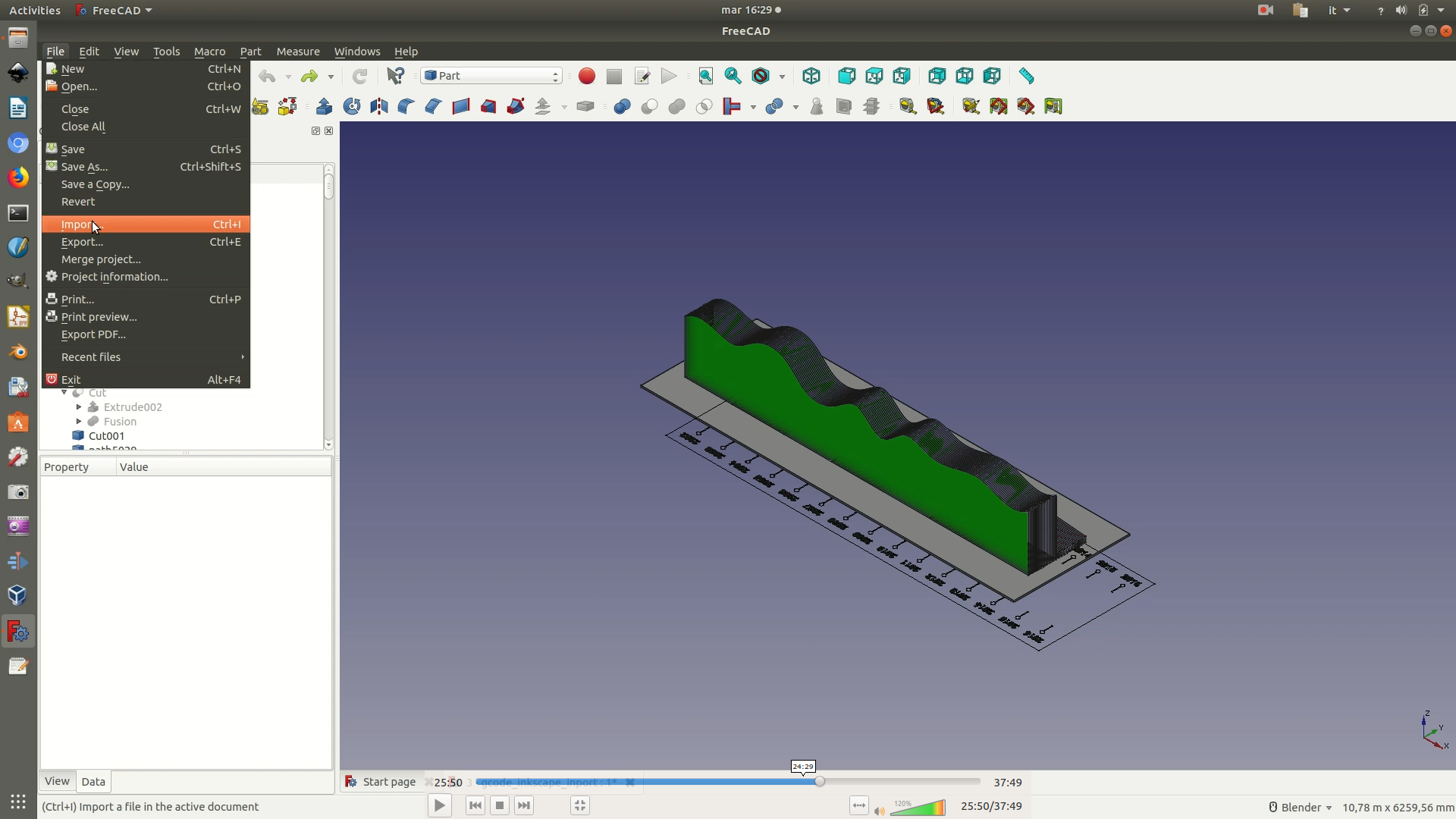
6. Switch back to the FreeCAD window, navigate to File > Import and select the exported .svg file. In the pop-up that appears next, make sure you select the option SVG as geometry (importSVG).
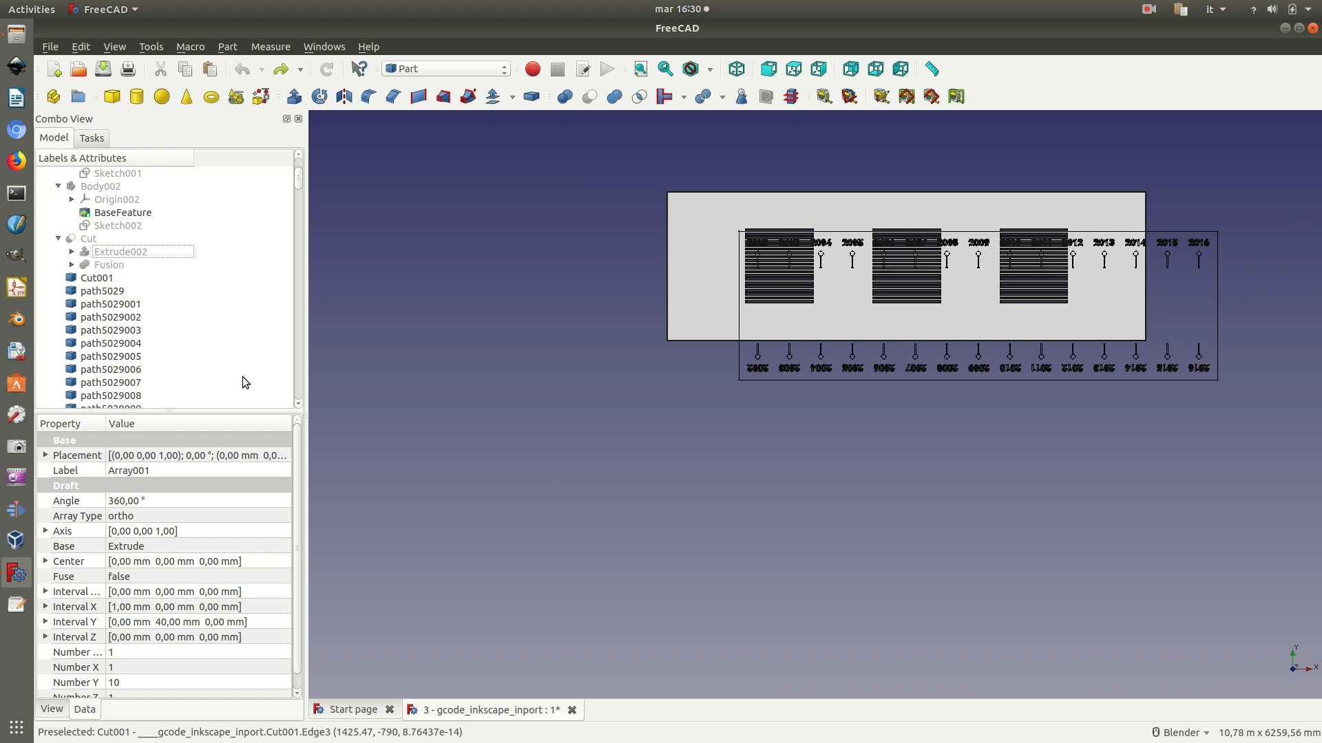
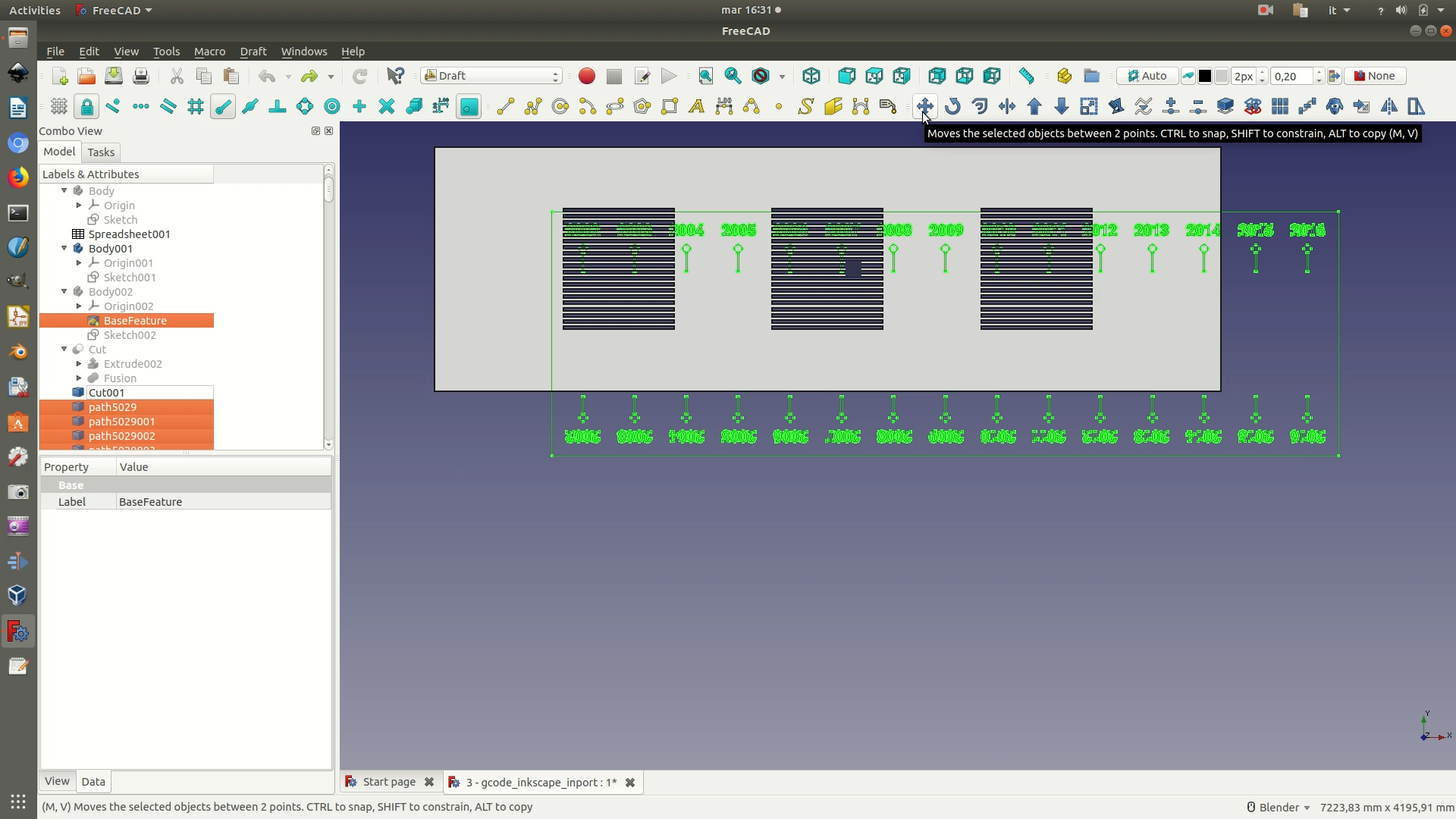
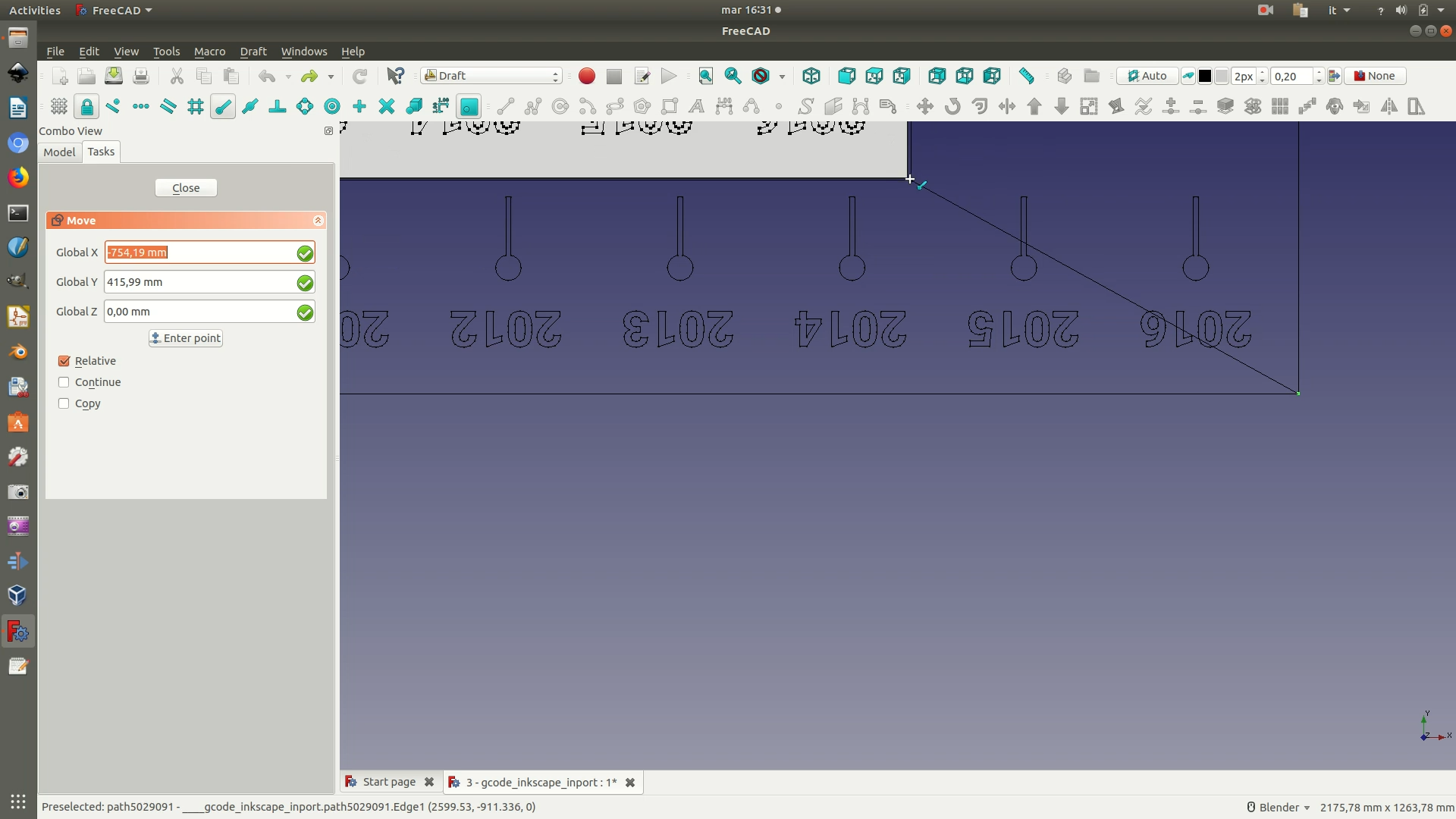
7. Switch to the Draft Workbench. Select the last two Array elements from the left sidebar and hide their visibility, so that you can clearly see the whole base component and the imported text/graphics. Go through View > Standard Views > Top to have a clear view of all the elements. Select the rectangle containing the text/graphics via Edit > Box Selection. On the menu, go to Draft > Move and click on one of the corners of the rectangle with the imported text/graphics. Then, click on the corresponding corner of the object’s base, as shown in the last of the images below. This will perfectly align your graphics to the base.
8. You can now hide the base (the last Cut component on the left sidebar) and delete the 4 segments forming the rectangle that contains the text/graphics, so that your results look like the following image.
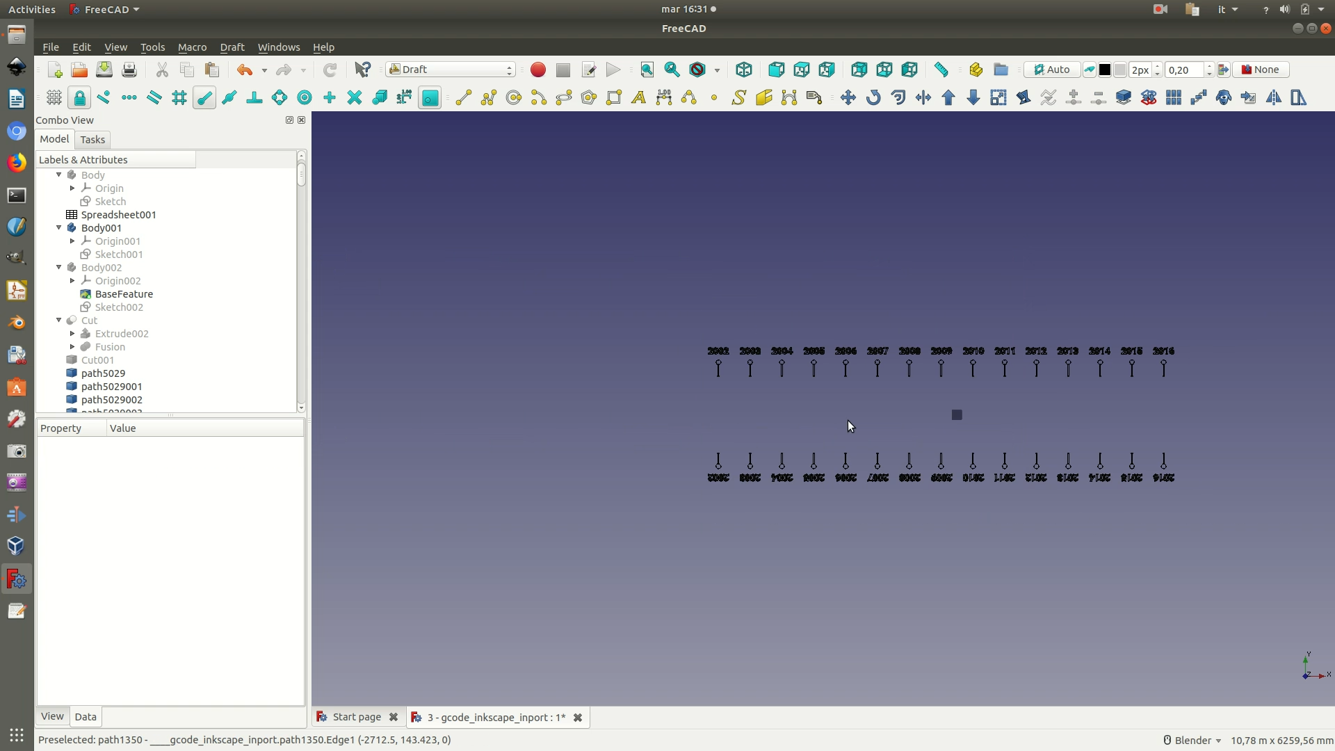
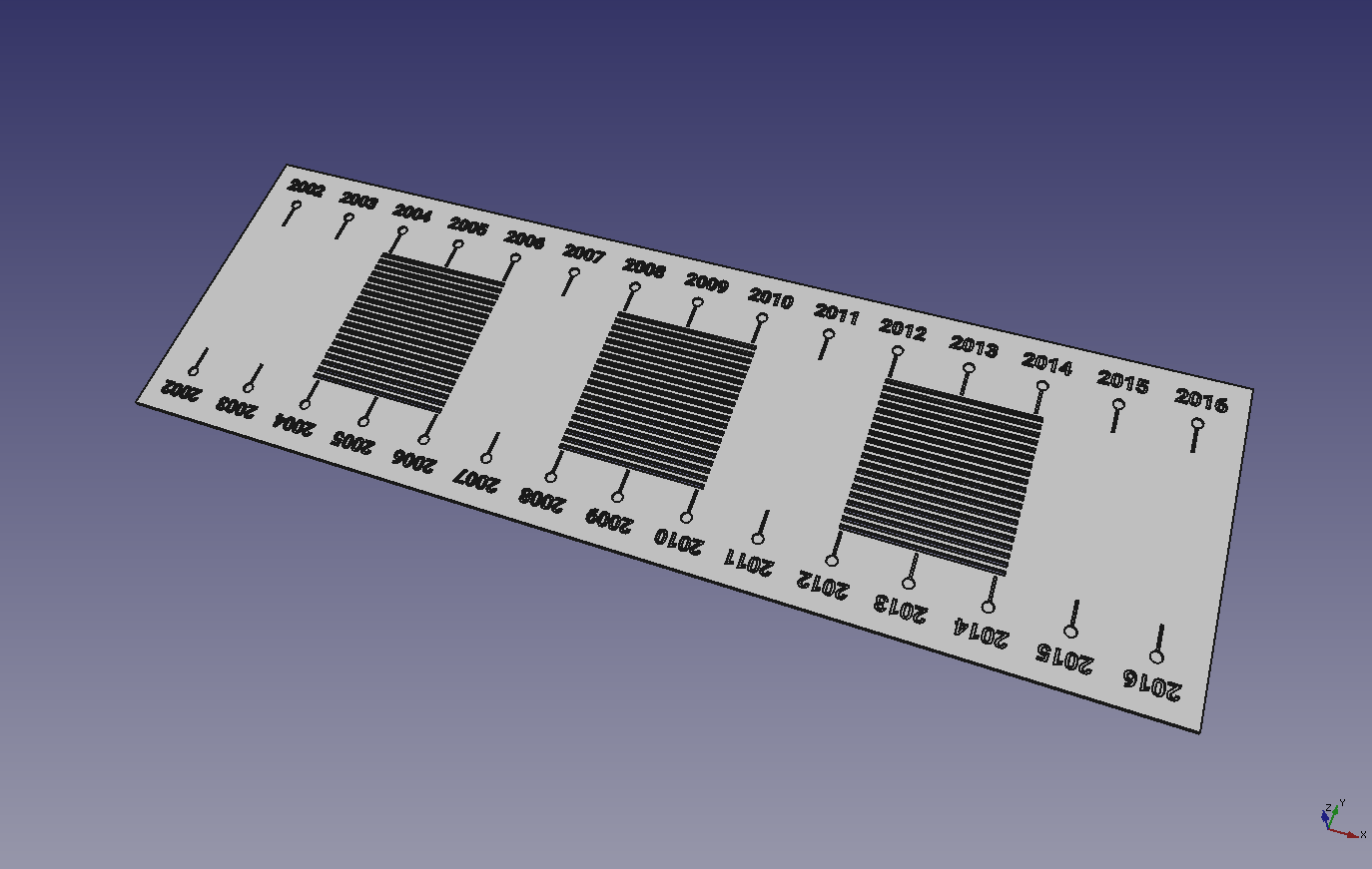
9. Switch to the Part Workbench. Select all the text/graphics element with a box selection and extrude them via the Part > Extrude command. On the left pop-up panel that now appears, assign a length of -10mm.
Note: if your computer freezes or crashes at this point, it might be that it is not powerful enough to handle the calculation. If you suspect this is the case, work in sections and select + extrude only a part of the text/graphics element each time.
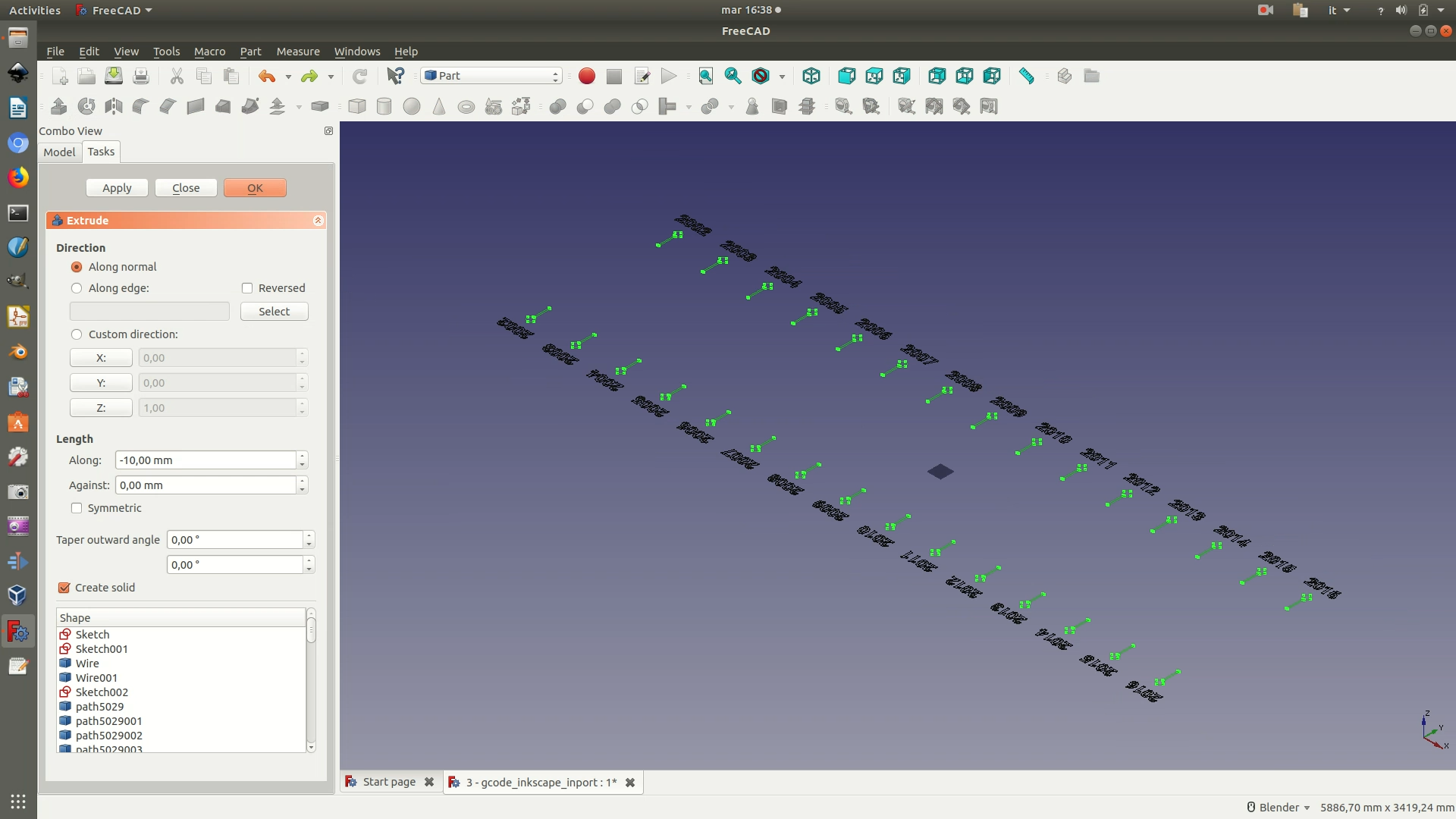
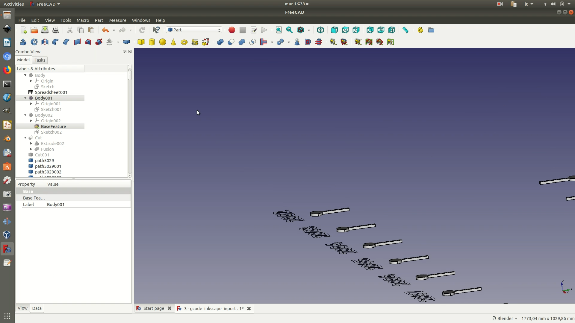
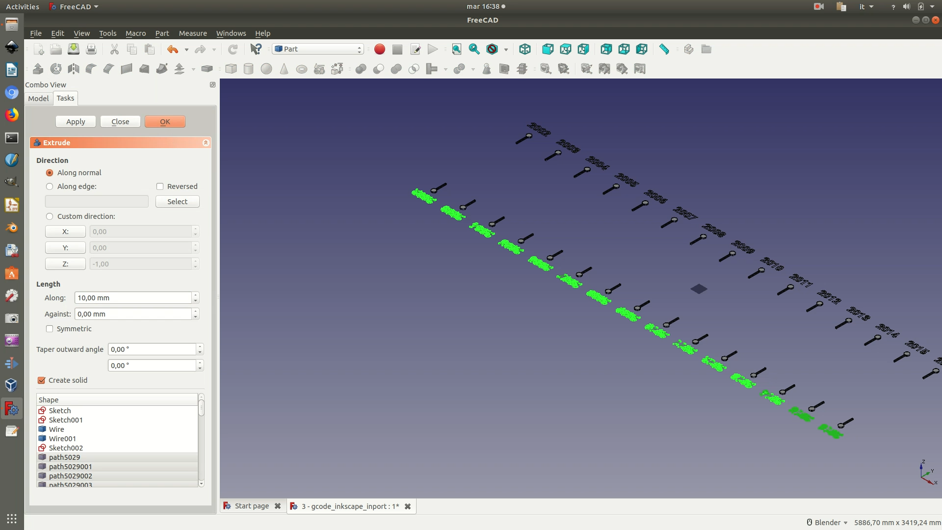
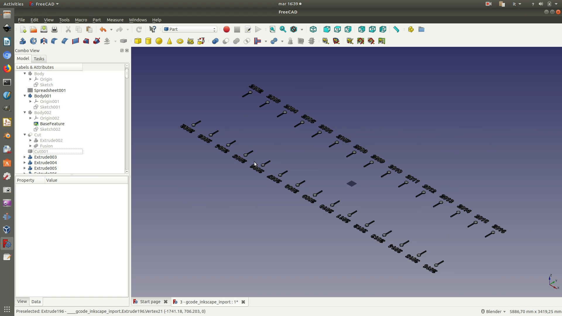
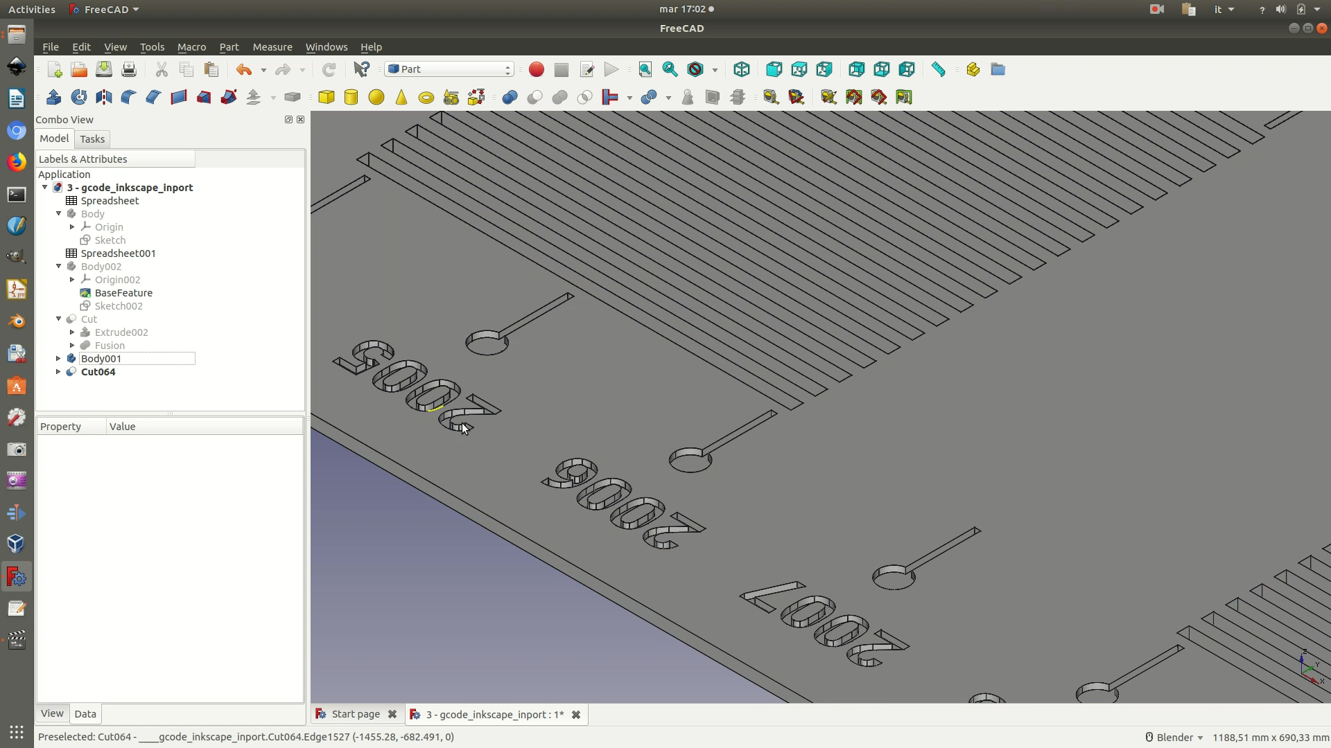
10. As you can see, because of how extrusion works, it didn’t handle all the letters and numbers as desired. This is due to the fact that the command has no way of detecting the difference between a line and what we perceive as a “hole” (technically: counter). To remedy this, we need to make a Boolean cut operation on all the letters. For each of the letters/numbers that present this problem, select the outer shape and then the inner shape (in this order) and then click through Part > Boolean > Cut.
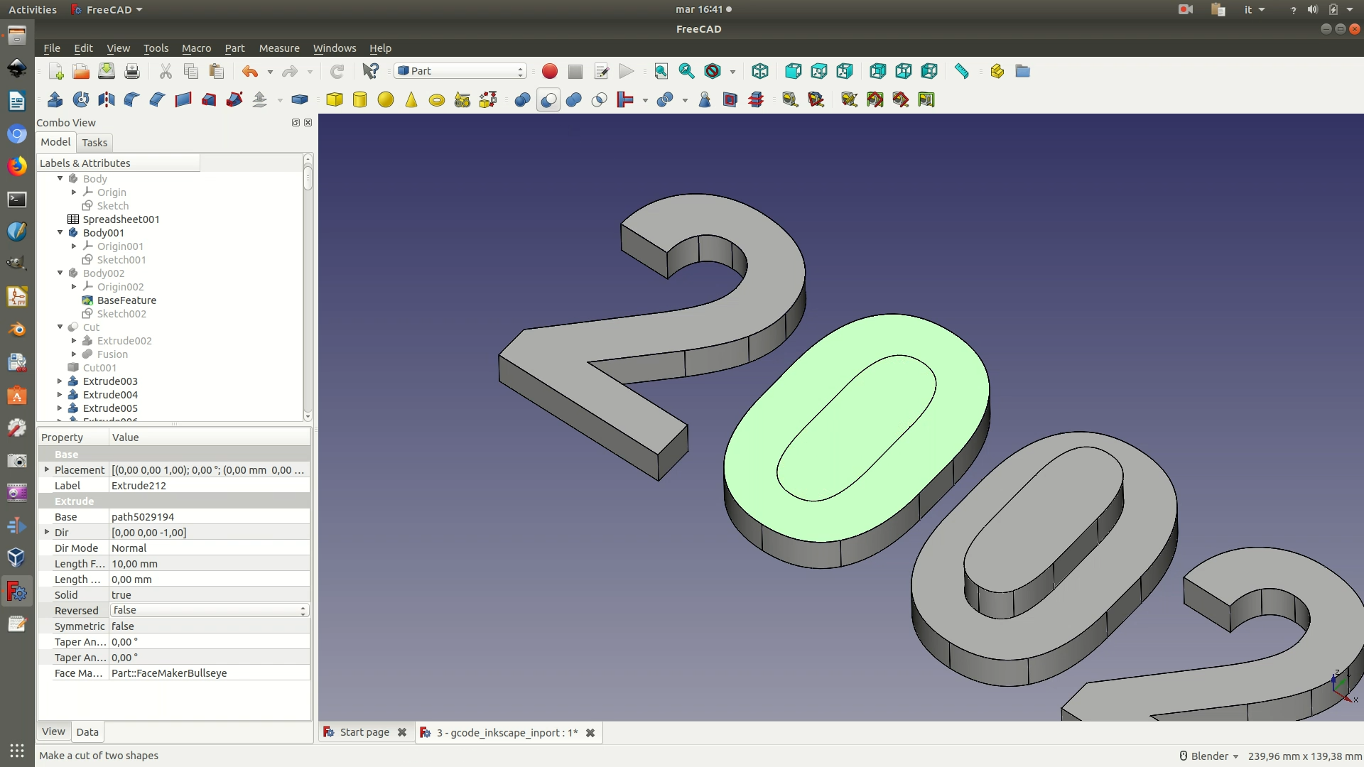
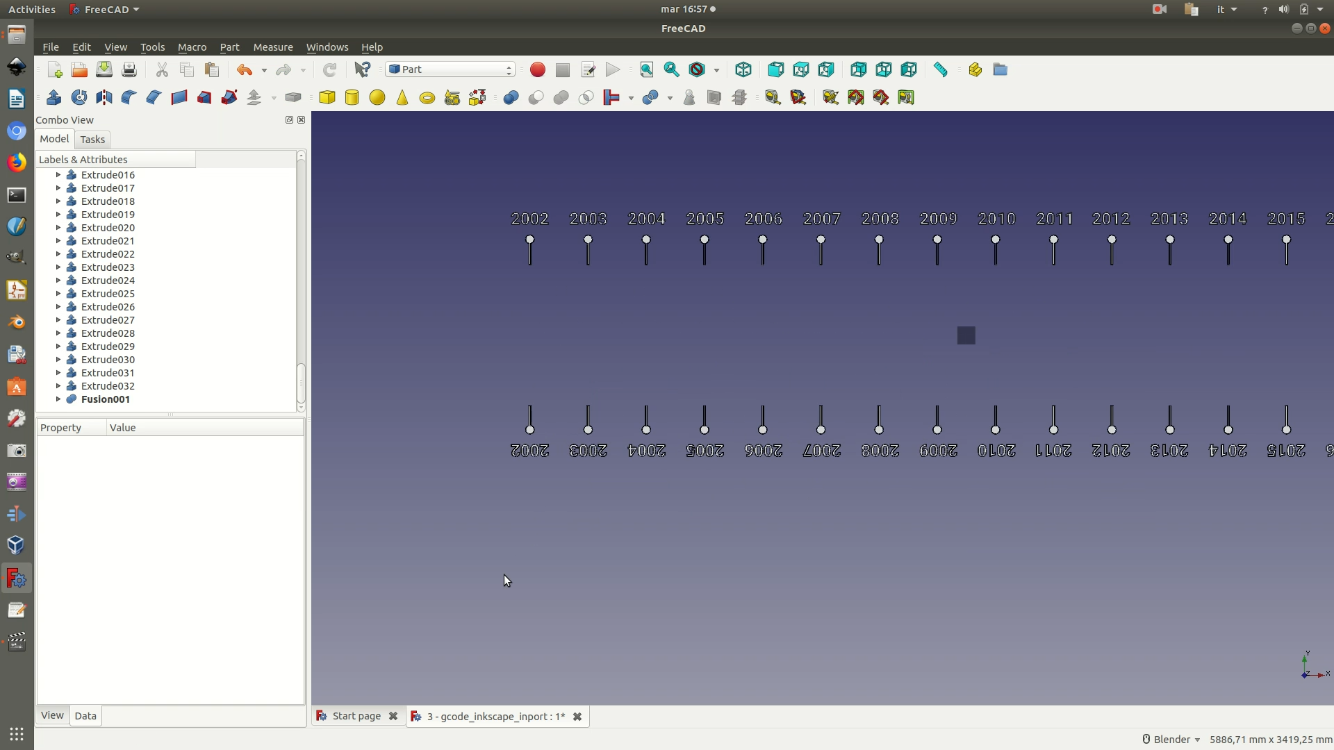
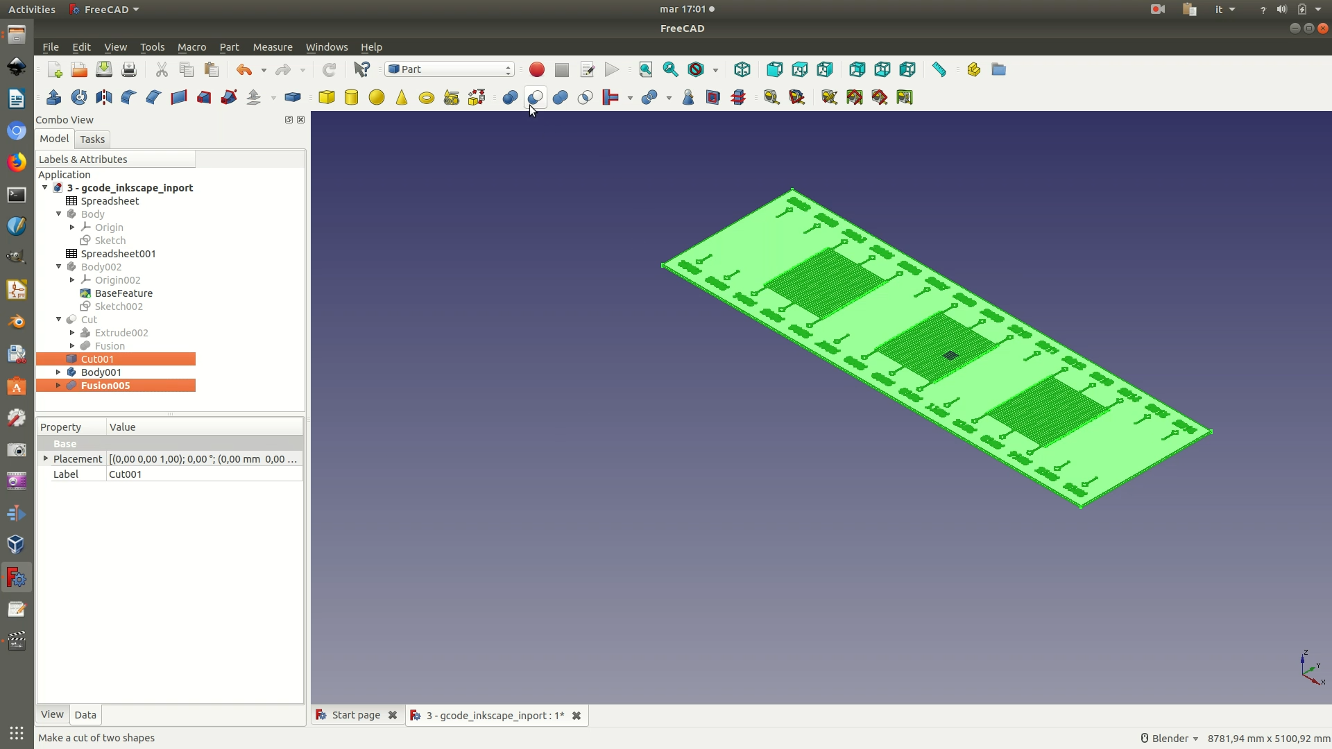
11. Select all of these text/graphics elements and perform a Boolean union, by clicking through Part > Boolean > Union. All of these components are now grouped in a single Fusion element in the left sidebar, so that you can now select all of them at once.
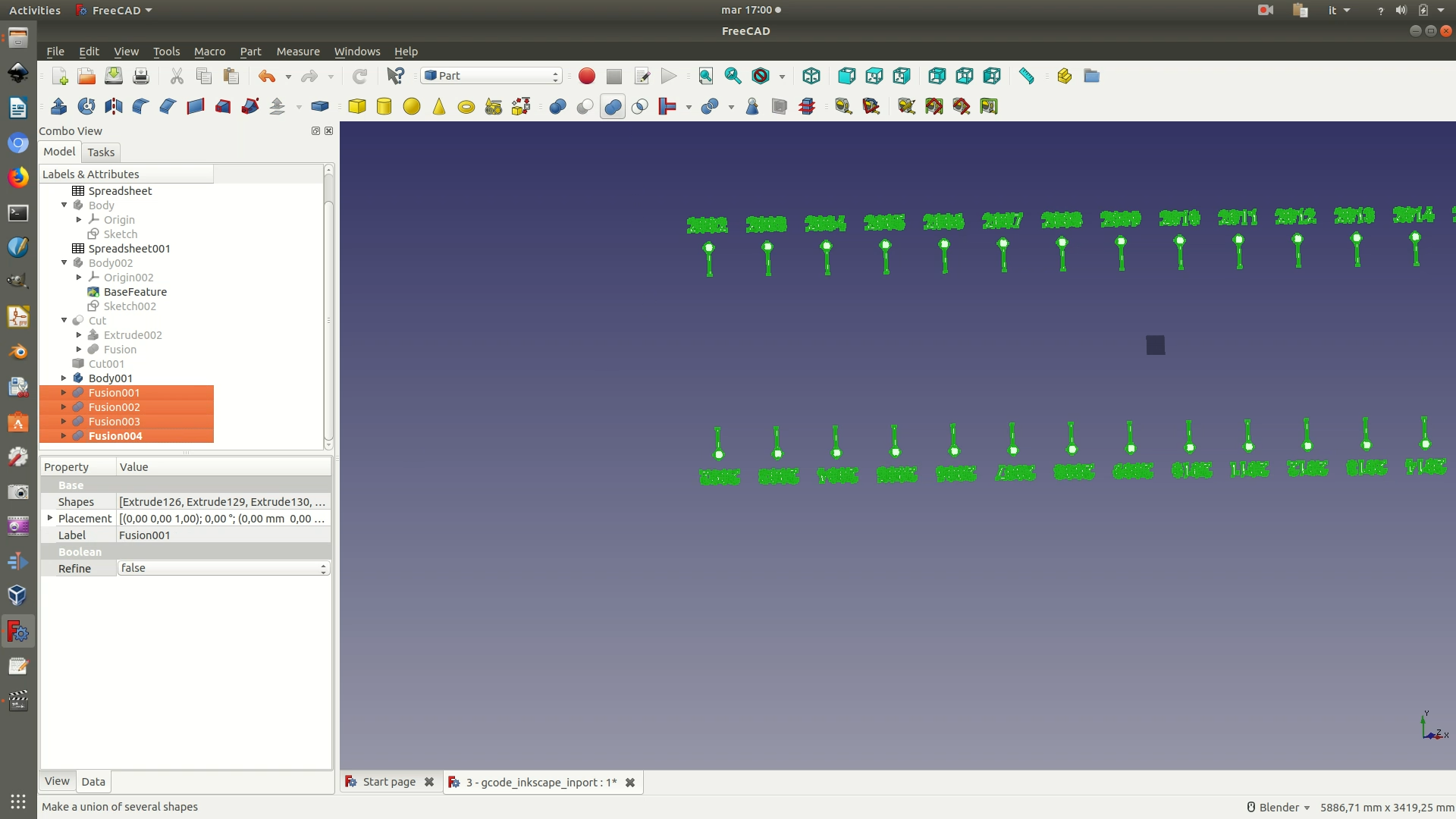
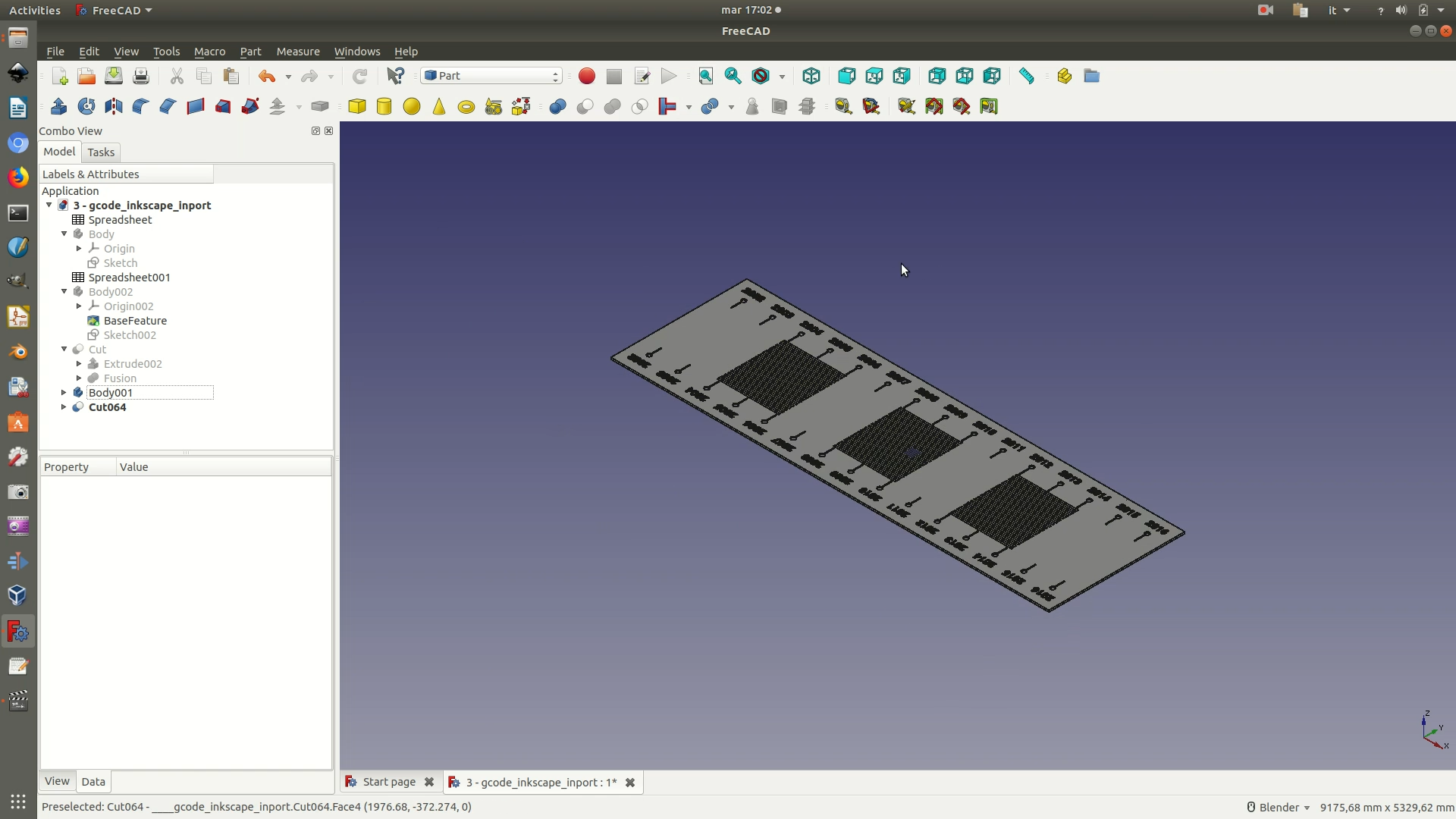
12. From the left sidebar, select both the last Cut element (the one with the base) and the last Fusion element (with the text and graphics). Make sure you select them in this order. Then perform a cut by clicking through Part > Boolean > Cut. Depending on how powerful your processor is, it might take a few minutes for the calculation to be completed. Your file is now ready to go into fabrication, so make sure you save it.
A few words on the graphics and text
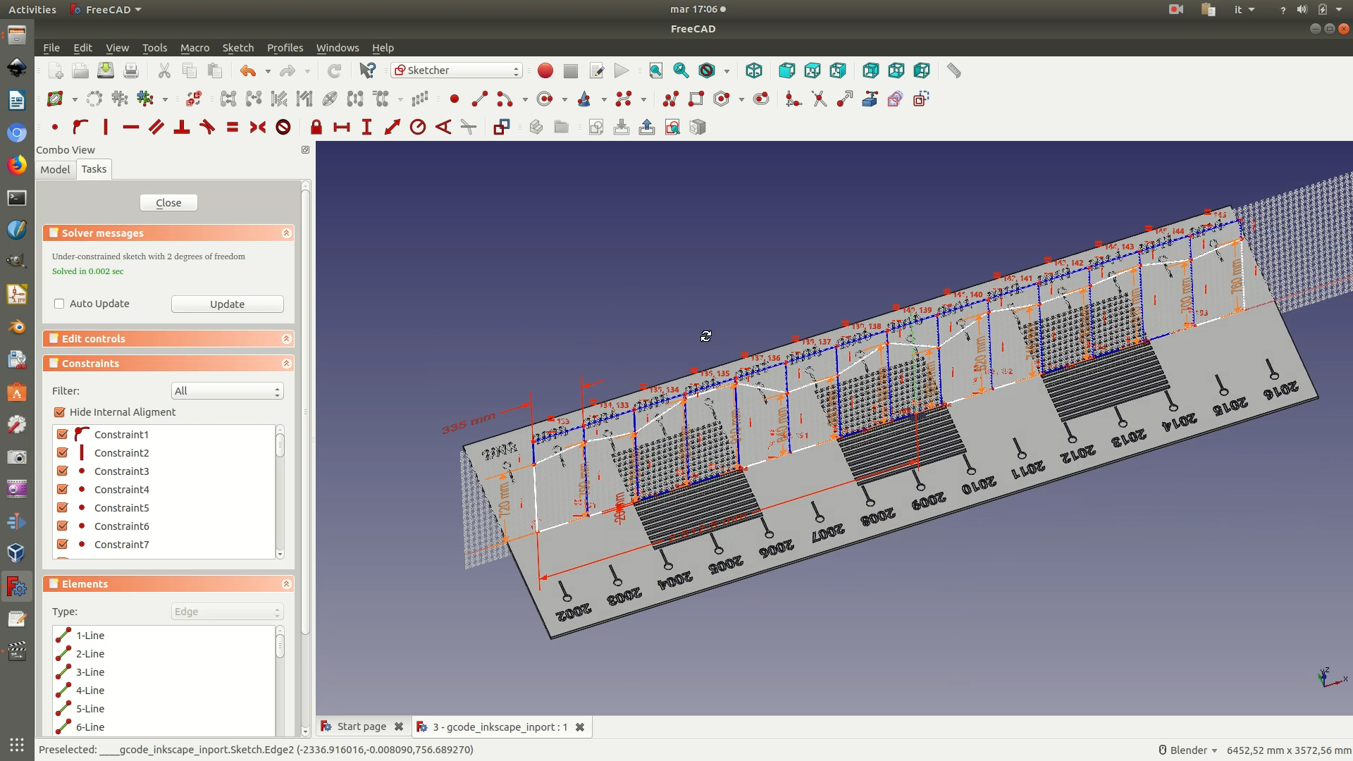
To keep things simple, this tutorial has kept the graphics and text elements to the minimum. It is pretty easy, however, to add more elements, like titles, annotations, legends and so on. The level of complexity you can achieve will depend greatly on your previous knowledge of graphics notions and of the software. Additionally, it will depend on the kind of machines you have access to. If you only have a CNC milling machine to engrave, then this means that you will manually have to fix the holes in every single letter of your text. Something that can quickly escalate to be a tedious and long task, prone to errors (it’s easy to forget about a few letters). In this case, it is probably wise to stick to the basics and use other things (posters, stickers…) to provide more context. On the other hand, if you have a laser cutter/engraver, then the graphics can be quite complex, like in the suggested example below, as the .SVG file produced with Inkscape (or your software of choice) can be directly used to engrave, without the need to pass through FreeCAD.
