Assembly · Light Data Bars

In this phase of your project you will assemble the single milled and 3D printed components together to form the final data installation. The actual steps might vary slightly depending on the specs project. For example, you might want to apply paint and colors to your components before proceeding with the assembly. Keep in mind the main safety rules and procedures of manual work: wear gloves and sturdy shoes, keep feet and fingers away pinches and crushes, never lift heavy objects alone, etc.

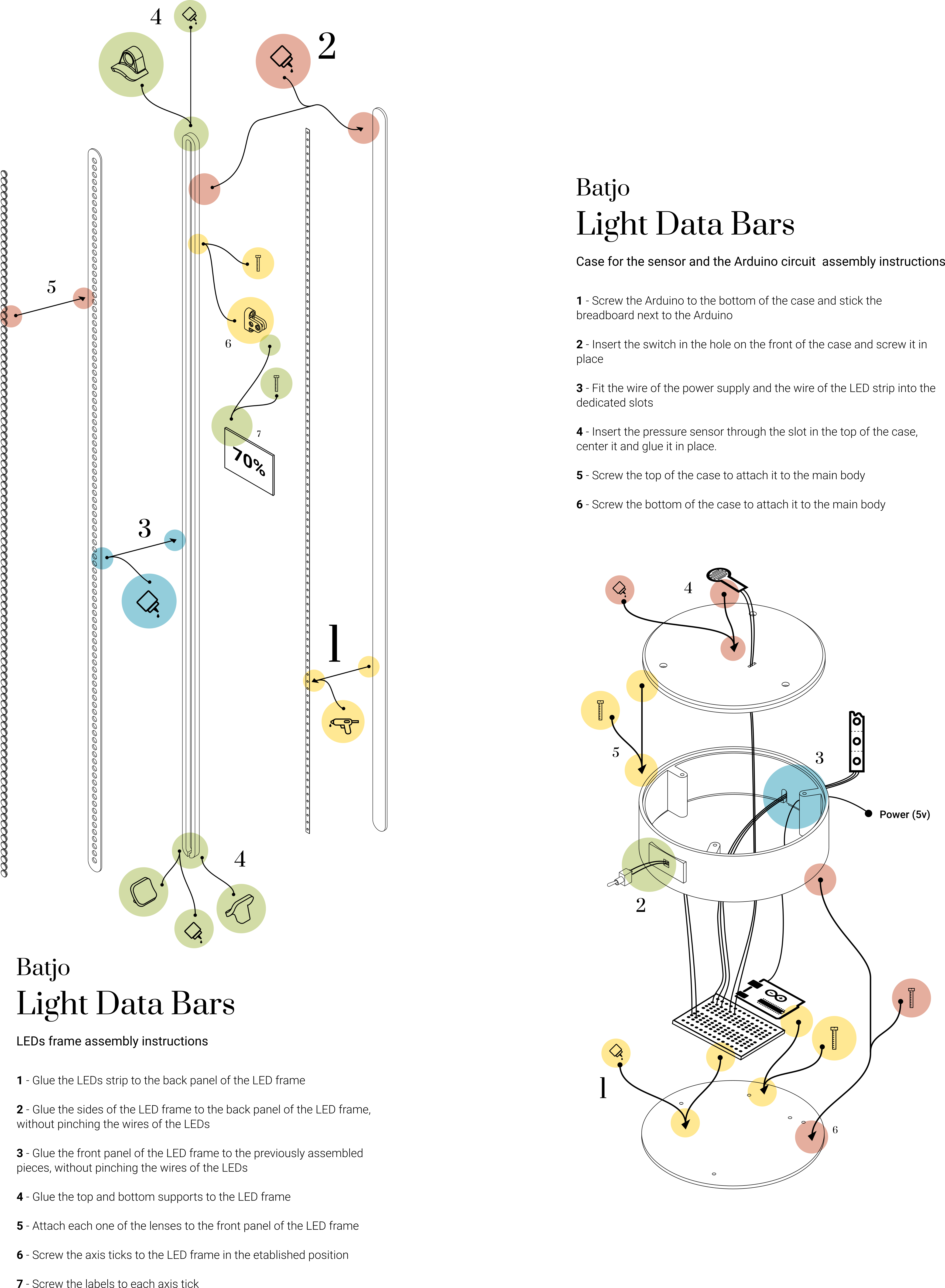
- Glue the LED strip to the back panel of the LED frame using a hot-glue gun. Try to use as little glue as possible so that the strip lays flat, without bumps, on the panel.
- Glue the sides of the LED frame to the back panel with the LED strip attached. Make sure the sides and the back are aligned and use a regular wood glue to seal them together. Be careful not to pinch the wires of the LED strip by checking that they pass through the slot carved at the bottom of the side panel.
- Glue the front panel of the LED frame to the previously assembled parts. Make sure the sides and the front are aligned and use a regular wood glue to seal them together. Check that the wires of the LED strip are still all in the slot, so that you don't accidentally glue them in between the layers.
- Glue the 2 bottom PLA support legs to the bottom of the LED frame and the 1 top PLA wall support to the top of the frame. Use a strong glue suited to attach together plastic and wood.
- Insert each of the 100 PLA LED lenses to the front of the LED frame. The lens should fit just right, you so don't need any glue to secure them, but you might need to push a little to make them fit inside the holes .
- Position the (three) axis ticks to in designated locations. For example, if the bar has 100 LEDs and the first tick signals 25%, position it next to the 25th LED. The ticks are as wide as the side panel of the LED frame, so you can use the sides of the front and back panel as guidelines to place the ticks in a straight position. Use 3 screw for each tick to fix it in place (type of screws: 10mm long 3mm diameter).
- Screw the labels to the corresponding ticks using 2 screws for each label (type of screws: 10mm long 3mm diameter)
- The Arduino board has 4 holes where you can fit 4 screws. Use these holes to screw the Arduino microcontroller to the bottom component of the case (type of screws: 10mm long 3mm diameter). Make sure that the bottom component is in the right position: the bottom side is the one with the small supporting feet. Be careful not to damage the circuit with the breadboard. Stick the breadboard next to the Arduino. Most standard breadboards will have a sticker at the bottom, which you can peel to stick the breadboard on the case. If your breadboard doesn't have this sticker, you can also glue it using a hot glue gun.
- All switches come with a nut and a lock washer. Unscrew the first nut and the first washer from the switch. Insert the switch in the hole that is on the side component of the case. The side component has an open slot on one of the rims: make sure this slot is at the bottom. Insert the washer (first) and the nut (second) back in the switch and screw them tight again to fix the switch in place.
- Fit the wire of the power supply and the wire of the LED strip through the slot at the bottom of the side component of the case. You might want to temporarily tape the wires in place until you complete the next step which will close the slot.
- Insert the pressure sensor through the top component of the case. Make sure that the top component is in the right position: the top side is the one with the chamfer.
- Screw the top component of the case to the side component using 3 screws (type of screws: 10mm long 3mm diameter).
- Screw the bottom component of the case to the side component using 3 screws (type of screws: 10mm long 3mm diameter).

