Assembly · 3D Data Map

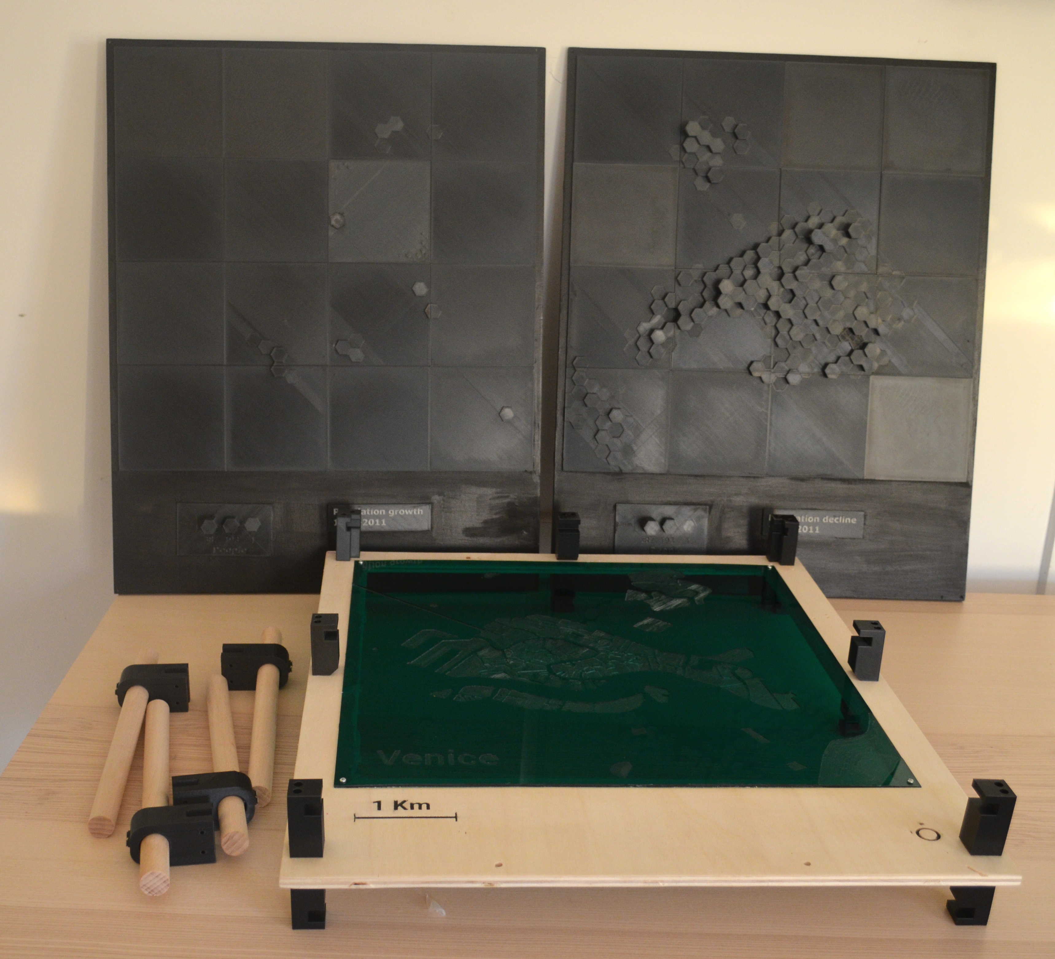
Note: as you can see from the above picture, we also built some support elements to keep the layers in place. This is because we couldn't hang the installation from the ceiling. We haven't uploaded to model and tutorial for such elements because they are very rudimentary, and we believe that they hinder an optimal, 360° fruition of the 3D Data Map. We encourage you to find a solution that allows users to easily raise and lower the data layers on to the map and to be able to freely crawl and touch both the bottom and top data layers. Should you anyway wish to fabricate and assemble a support structure like ours, get in touch and we'll send files and assembly instructions to create supports for either resting the installation on a table or for hanging the different components on the wall.
In this phase of your project you will assemble the single milled and 3D printed components together to form the final data installation. The actual steps might vary slightly depending on the specs project. For example, you might want to apply paint and colors to your components before proceeding with the assembly. Keep in mind the main safety rules and procedures of manual work: wear gloves and sturdy shoes, keep feet and fingers away pinches and crushes, never lift heavy objects alone, etc.

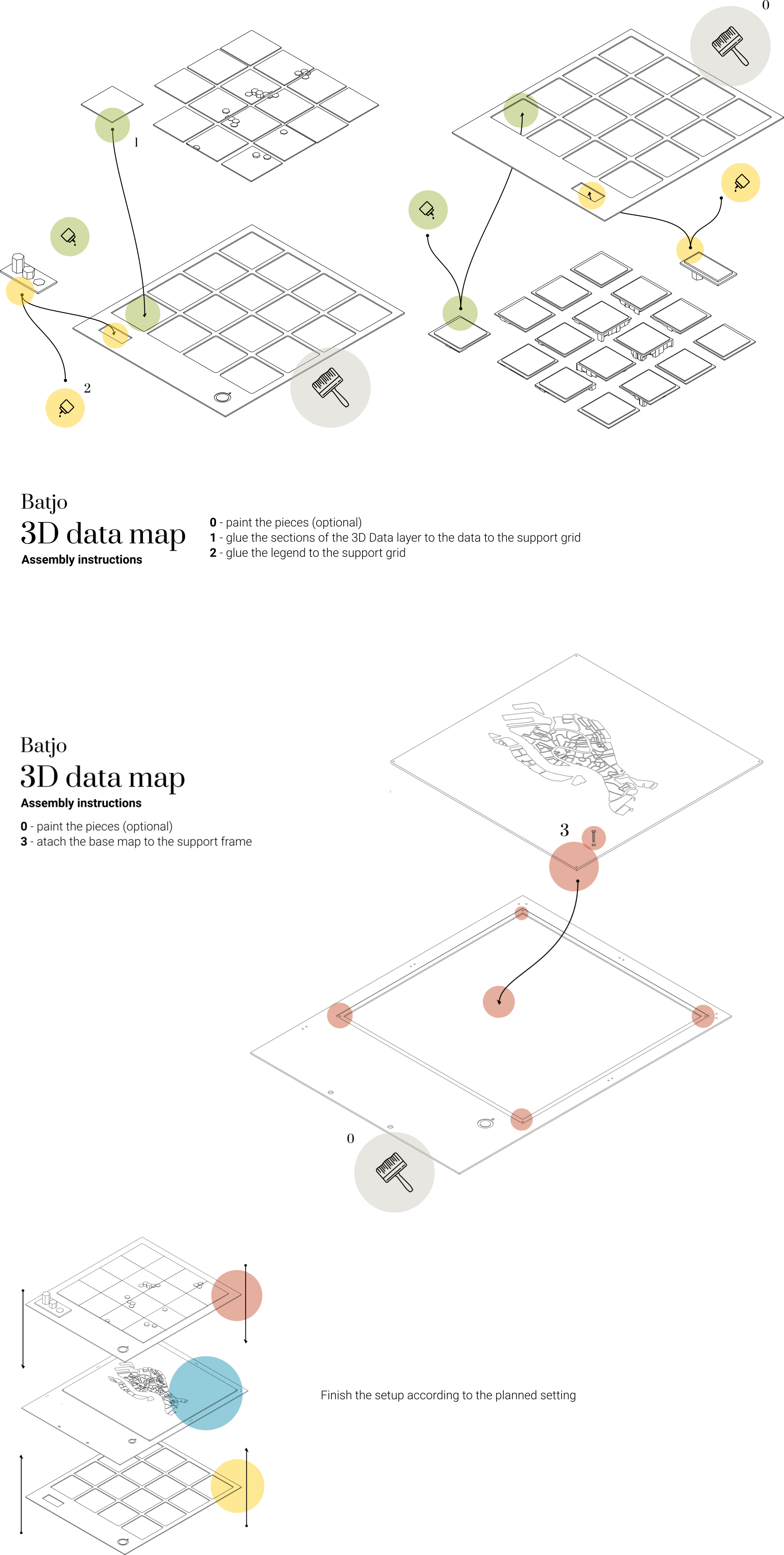
- Paint each piece according to the desired appearance (color) and environmental needs (like waterproof paint for outdoor installations). Make sure the paint has dried up completely before moving on to the following steps.
- Position the sections of the 3D data layer on the support grid and glue them on it. The data grid is designed so that each of its sections has a unique combination of border radiuses, matching the combination of only one section of the 3D data layer. This way, you will only be able to fit the right data section into the right grid section. To save time, however, it is convenient that you print the data layer sections in a logical order and position them on the corresponding section of the support grid as soon as they're printed. It could be that the 3D printed sections have some small imperfections that prevent them from smoothly fitting in the data grid. In this case you can sand the edges lightly with some fine-grained sanding paper.
- Position the 3D printed legend element on the support grid and glue it on it. It could be that the 3D printed parts have some small imperfections that prevent them from smoothly fitting in the data grid. In this case you can sand the edges lightly with some fine-grained sanding paper.
- Attach the plexiglas base map onto the frame, making sure it is in the right direction. (The frame has an arrow pointing towards what is the top). Once it is in place, fix the base map to the base by inserting one screw (3mm diameter, 8mm lenght) in each of the 4 corners.
Depending on how you will present the 3D Data Map, you will have to continue the assembly in different ways. For example, if you are hanging it from the ceiling, you will need to drill holes in to the 2 support grids and in the base map support frame. If you plan on hanging the base map and the data layers to the wall, or having it sit on a table, get in touch, and we'll provide you with the necessary files and instructions.

