Fabrication · 3D Data Map
Part 1.e - The legend - engravings (CNC Milling GCode)
Full Video Tutorial
Workflow explanations
1. Open FreeCAD and load the .fctd file containing the support grid.

2. Switch to the Path Workbench. This workbench allows you to generate the machine-readable paths that instruct the CNC milling machine on the movements necessary to replicate the designed object. Select the whole object and go through the menu Path > Job. In the dialog box that appears, leave the default options and click OK.
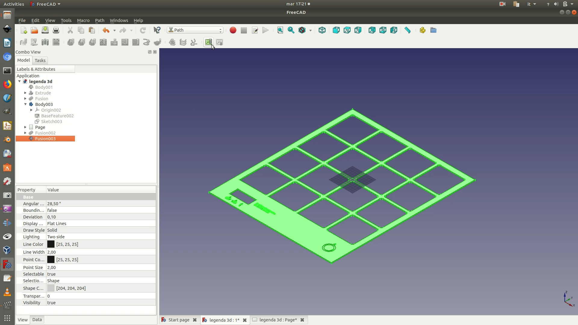
3. A transparent rectangle enclosing your shape should have appeared on the main window.
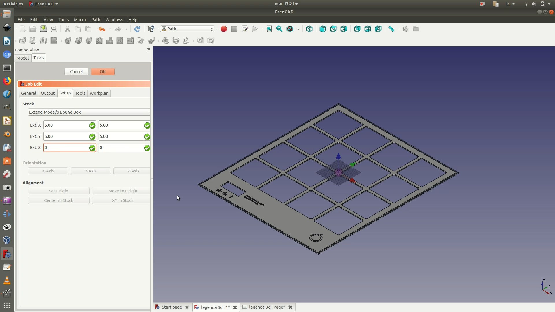
The rectangle is called “stock” and it represents the area of space from which the shape will be carved out or engraved. At the same time, a Job edit< pane will appear on the left. In this panel, you need to set the size of the margins you want to apply around your shape. The boundaries of the shape plus these margins define the size of the stock. In this case, we apply a margin of 5mm on both the X axis and Y axis. For the Z axis, on the other hand, we apply a margin of 0 mm. This way, the machine will cut all the way to the bottom of the sheet of wood.
Once you have defined to stock, you need to define the origin point of the machine’s movements. With your mouse, select the bottom left corner of the stock and click on the command Set Origin from the left selection panel. If this has been carried out correctly, you will notice that the Cartesian plane with the red, green and blu arrows has moved so that its origin corresponds to the corner you have just set as the origin. See image below for clarification.
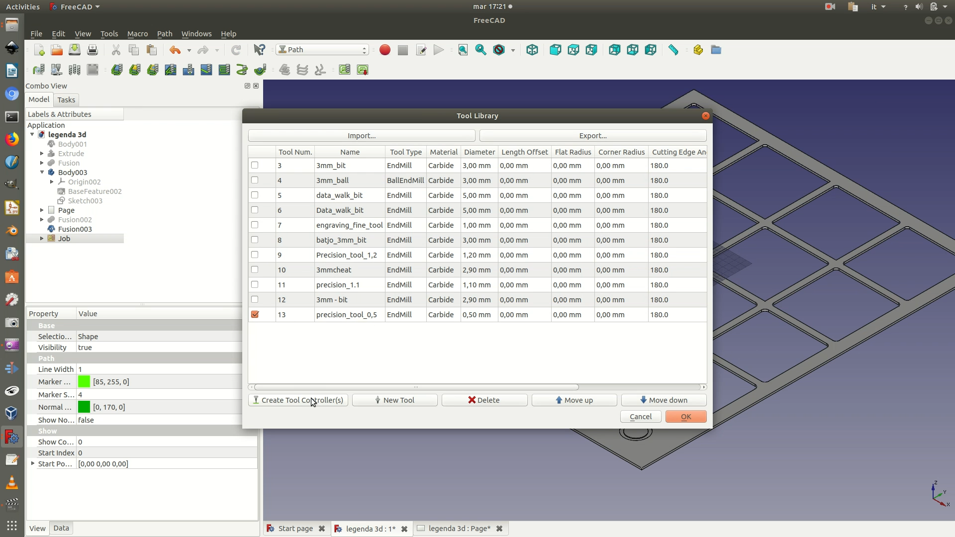
4. Declare what type of milling tool you are going to use to perform the cutting operation. Go through the menu Path > Tool Manager. A pop-up window will appear, with a tool library containing information on several milling tools their technical characteristics. Note that this library is build manually and gradually, as you add new tools you need to work with. In your case, thus, it is likely that the pop-up window will show you an empty library. To add a new tool to the library. Click on New Tool. You will be promoted with a form that allows you to define the specs of the tool you will be using and add it to your tool library. For this project, you will first need to define a milling tool that has at least the following specs: a type of EndMill and a diameter of 0.5mm. Clicking on OK will add this tool to your tool library.
Once the tool has been added to the library, mark the corresponding box in the tool library and click on Create Tool Controller(s). This way, the specified tool will be exported along with the other path instructions and will be used by the milling machine for its cutting task.
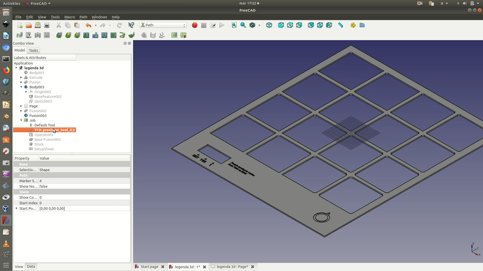
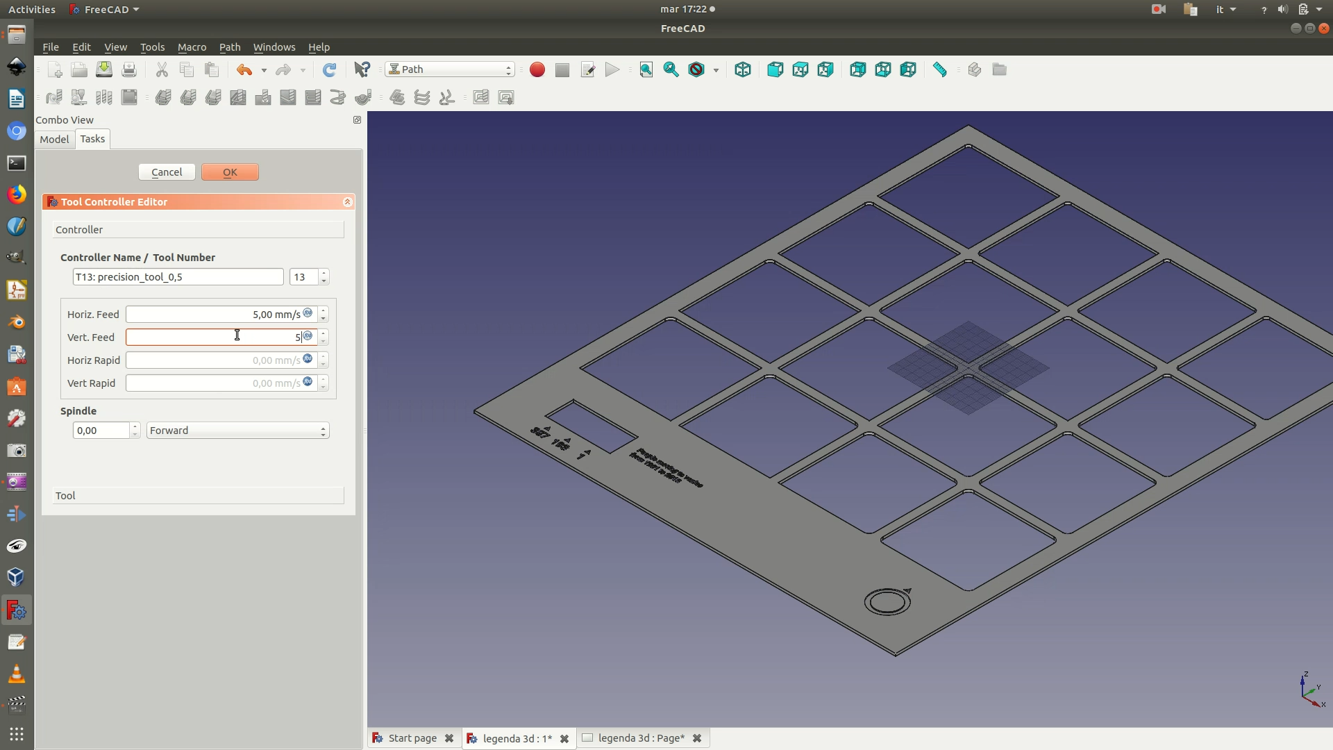
5. Because the created toll is a high-precision tool, you also need to set the speed of the movement of spindle. Double-click on the Precision tool element that is on the left sidebar. In the Tool Controller pane that appears on the left, set both the Horiz. Feed and the Vert. Feed to 5.00 mm/s.
6. Select a first batch of elements/letters/numbers that need to be engraved. (If you have a good CPU, you could also select everything in one go). Then go through the menu Path > Pocket. In the dialog box that appears, select the precision tool you had previously created (0.5mm diameter) and click OK. On the left, A Pocket Shape selection panel will now appear, change the Pattern parameter to ZigZafOffset and click OK. Zoom in to see the effect. This command tells the milling tool to “scratch” the surface by making a series of parallel linear movements.
If needed, repeat this step for until you have applied on all the text and graphics element that you wish to engrave.
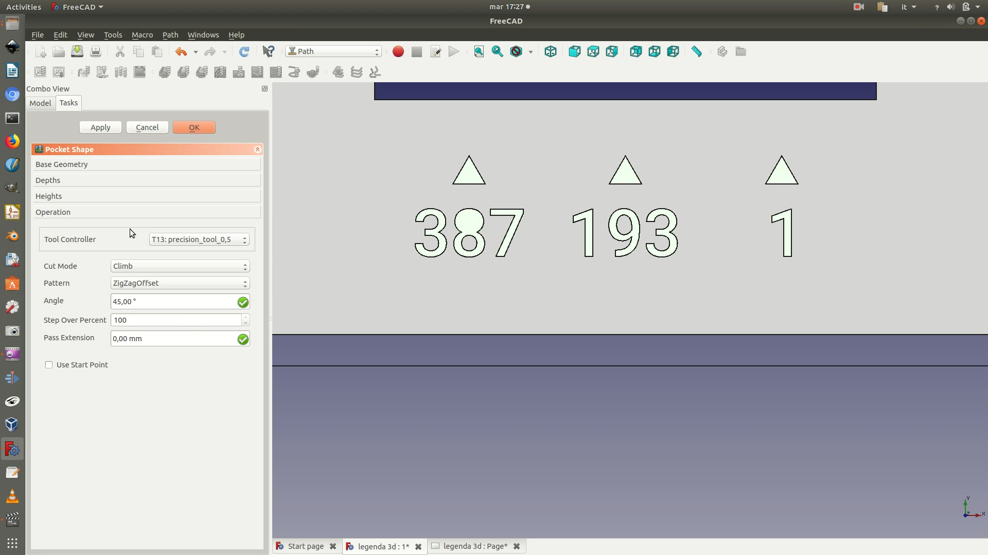
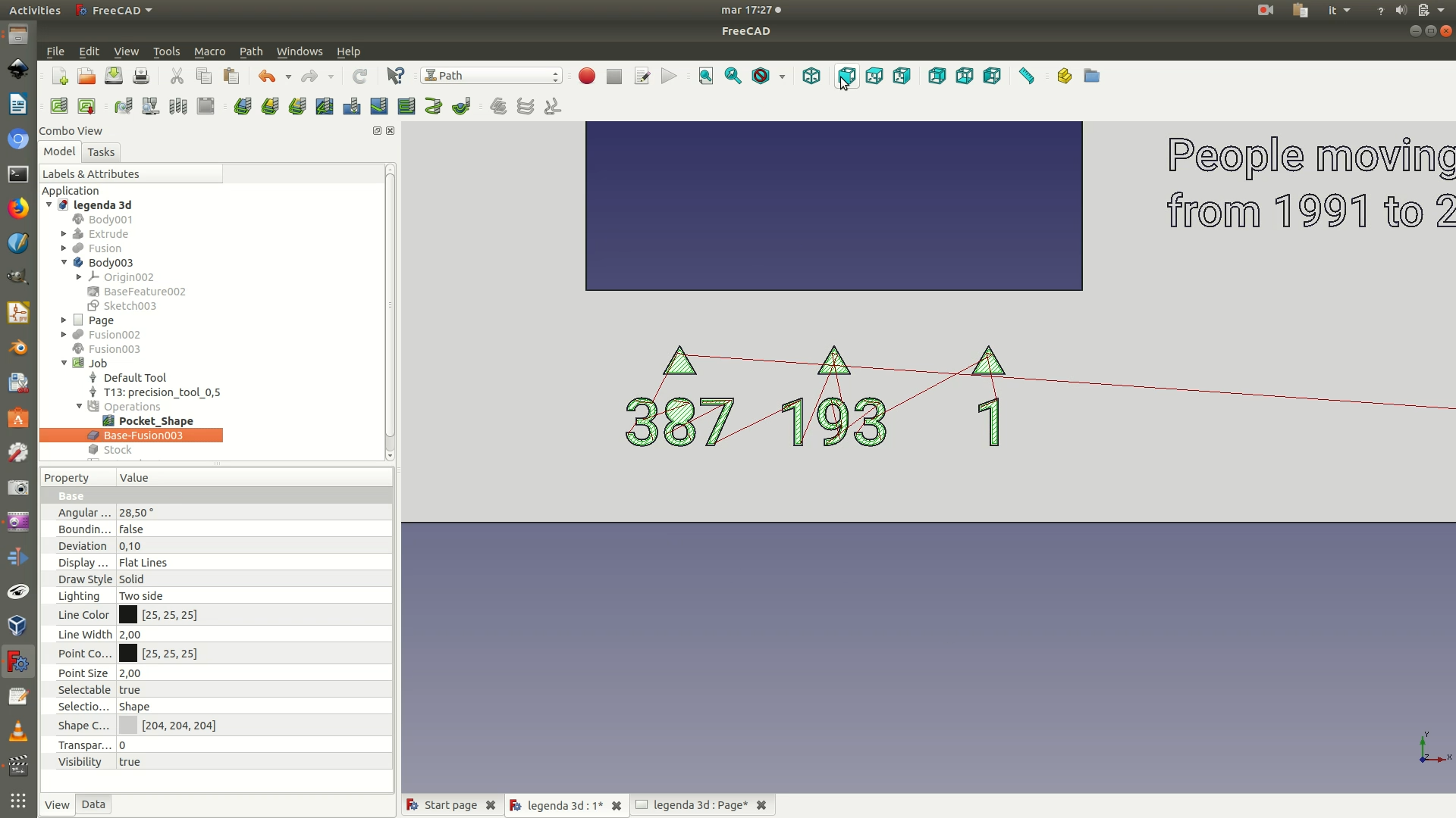
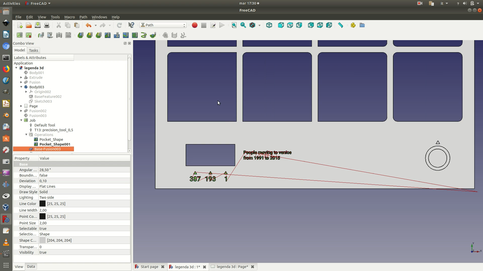
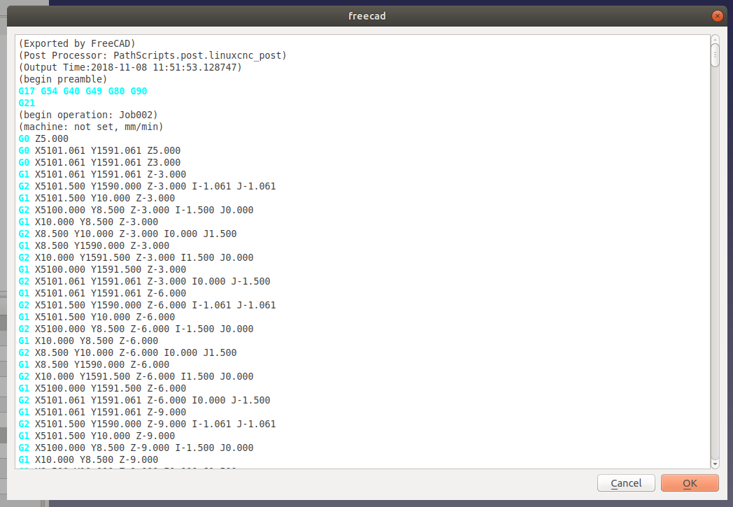
7. At this point, you’ve finished prepping the piece for engraving and you are ready for the export. On the left sidebar, you should have one Job element. Select it and click on File > Export. Select your destination folder, assign a name, and then select GCode (*.nc *.gc *.ncc *.ngc *.cnc *.tap *gcode) as a file type extension. After clicking Save, you will be asked to Choose a processor. Usually, the most versatile option is to choose linuxcnc_post. As a precaution, it is recommended that you first check-in with the lab where you will fabricate your objects, to make sure that you choose the option that suits their machines best.
Upon confirmation, a pop-up screen will appear with the text of your GCode. Depending on how powerful your CPU is, you might have to wait a few minutes before you receive confirmation of the GCode creation.
