Fabrication · 3D Data Map
Part 1.f - The legend - 3D reference (3D Printing GCode)
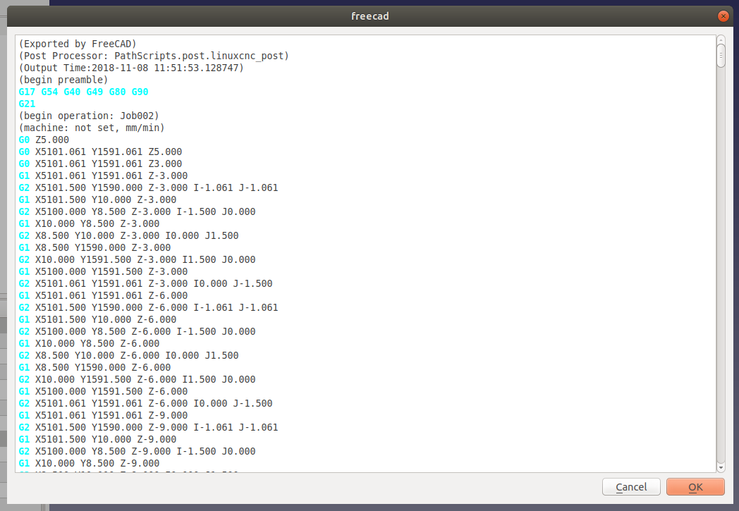
Full Video Tutorial
Workflow explanations
1. Open Slic3r. Slic3r is a software that processes a 3D model and generated instructions for the 3D printer, for example by slicing the volume into thin layers, creating supports for hanging elements, etc. The version of Slic3r used in this tutorial is a custom version tailored to the 3D printer used, a Prusa i3 mk3. The interface and the settings are however part of any Slic3r version you used. If you are using a general version of Slic3r, then you will need to set the configurations appropriately for your specific 3D printer. It’s wise to talk to the owner/operator of the 3D printer in this phase.

2. Click on the Add button from the top toolbar and import the .stl file for the 3D legend.
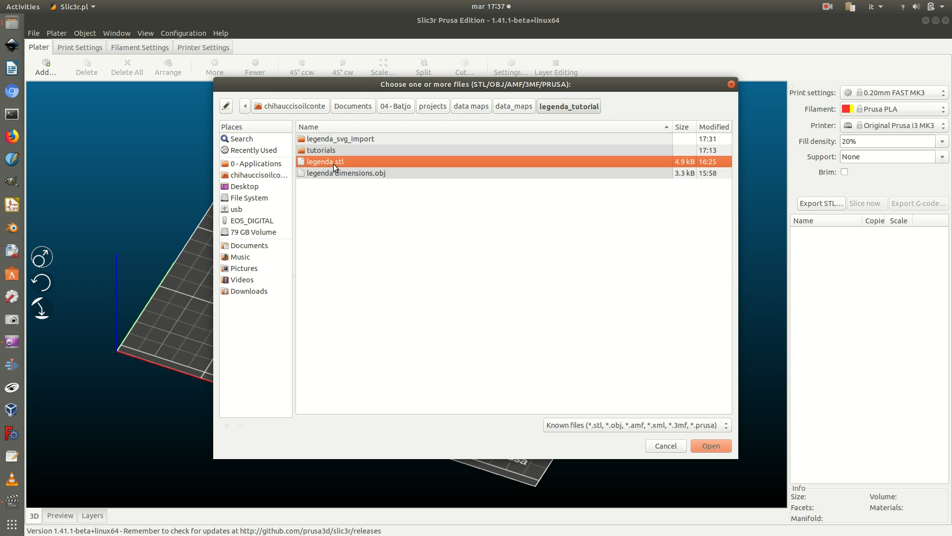
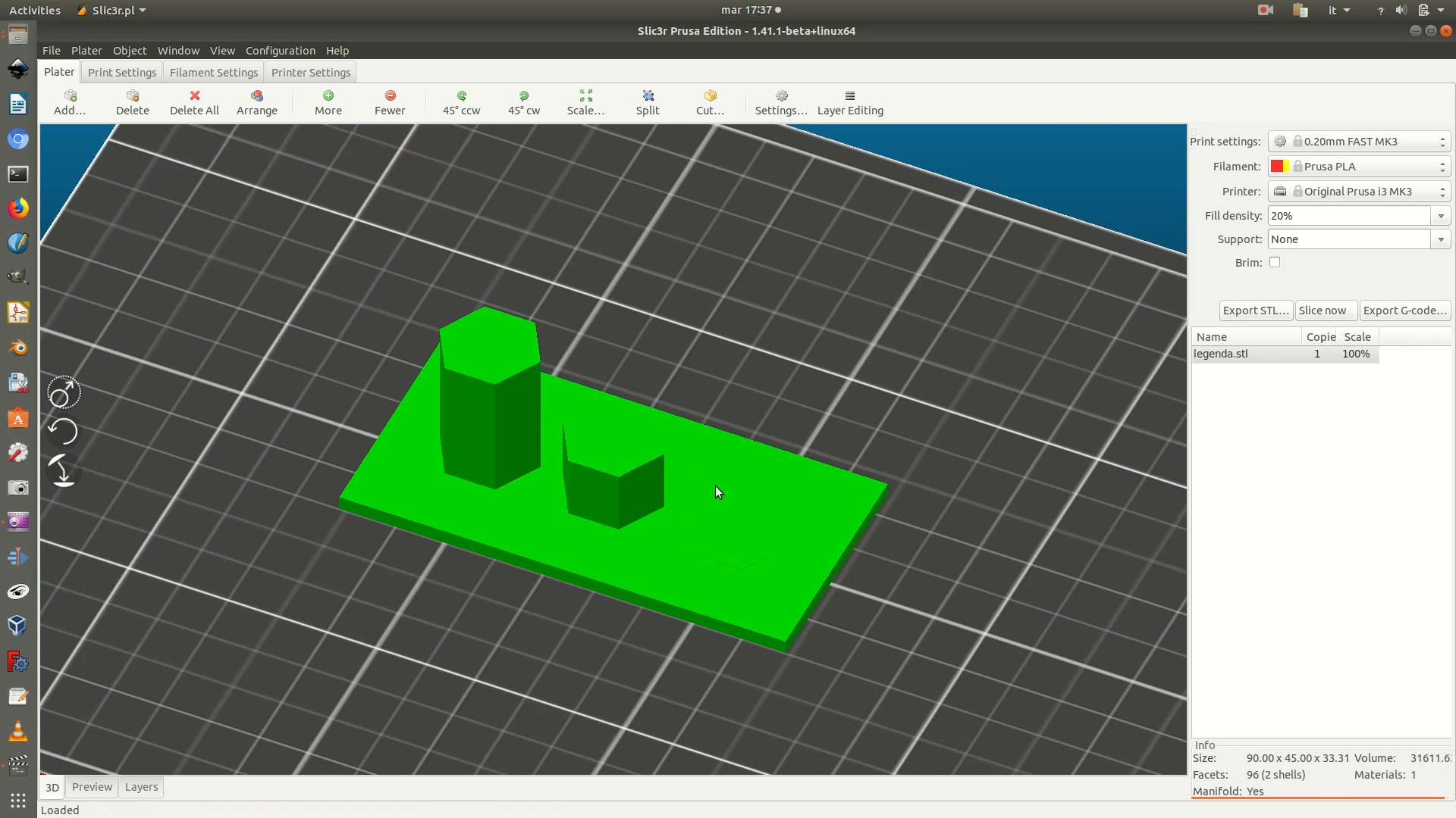
3. In the dropdown menus on the right, change the values to match the following options:
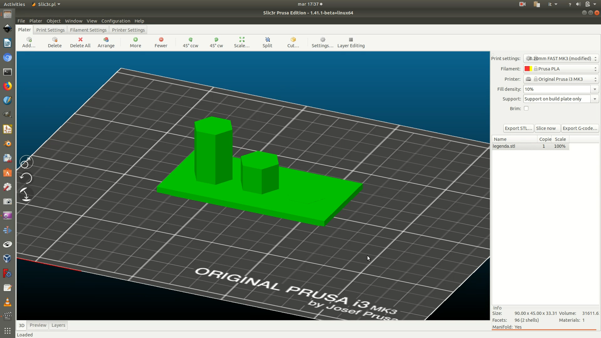
Print settings > 0.20mm FAST. This setting defines the height of each of the layers the objects gets sliced into for 3D printing.Filament > PLA. This setting defines the type of filament you will use to 3D print, and thus the temperature that the extruder has to reach in order to melt it and lay it.Printer >make sure the setup matches the printer you will use.Fill density > 10%. This value means that the only 10% of the piece will be filled, resulting in a light object with minimal material use. Because this is a decorative element that won’t need to endure particular pressure, a 10% fill density is certainly enough.Supports > Support on build plate only. This because the base of the object is narrower than the top, but we can’t flip it since there are 3D hexagons on the top. Setting this parameter will create supports for the hanging part of the base.
When you have defined all these parameters, click on Slice now.
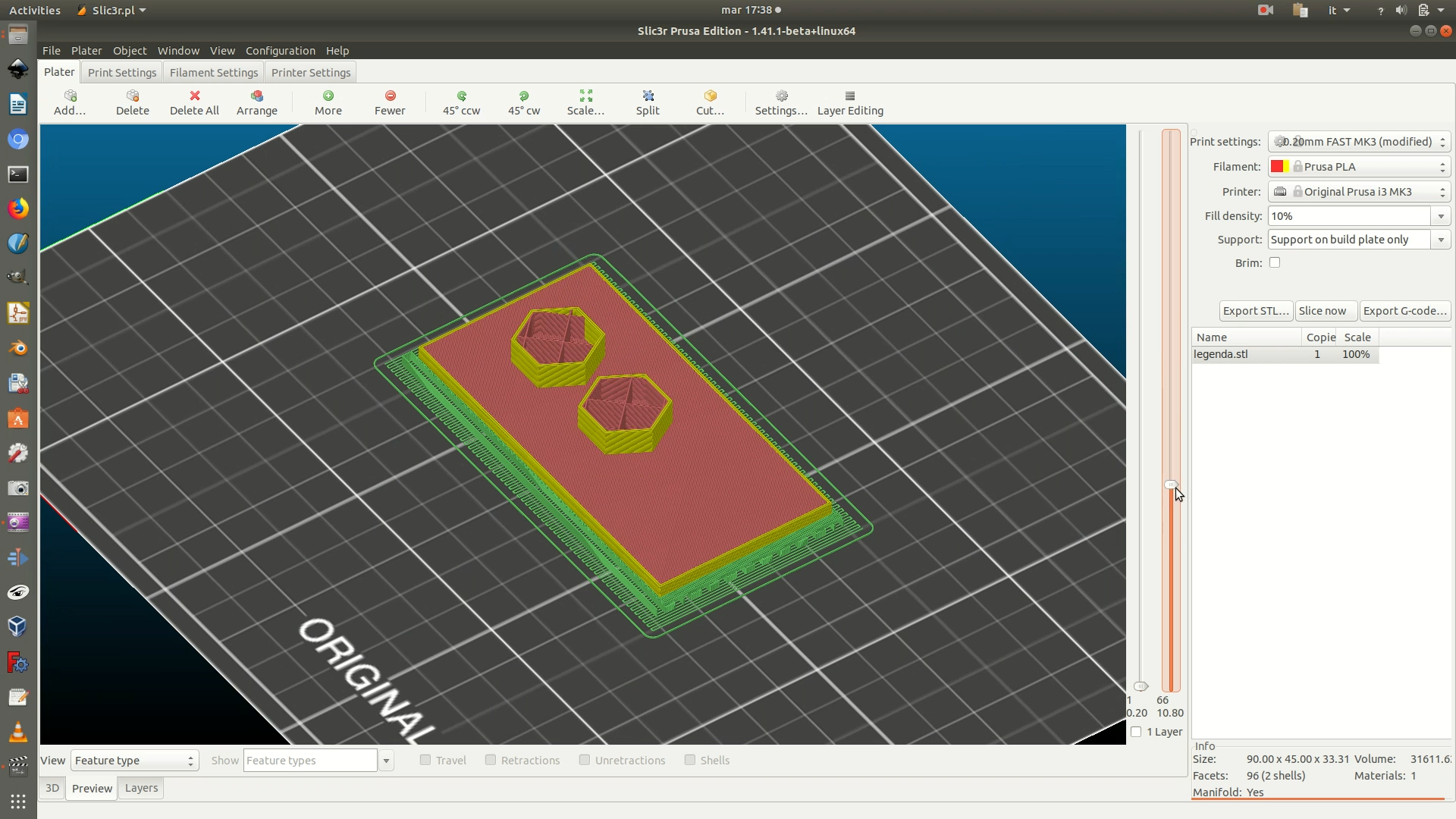
4. Click on the Preview tab, from the lower left side of the window. This will show you a preview of the movements the machine will make. You can play with the sliders on the right to check if the output is as desired. As you can see there are some green lines, representing the supports for the base. There are also some red structural elements inside the hexagons, these are additional supports created in the previous step as well.
5. Click on the Export G-code button on the right and save the file.
